BSM25GD120DN2 IGBT Power Module: 1200V 25A Sixpack Solution for Industrial Efficiency
BSM25GD120DN2 IGBT Power Module | 1200V 25A Sixpack Solution
Industrial Power Efficiency through NPT Technology
The BSM25GD120DN2 is a high-performance IGBT power module configured as a three-phase inverter (Sixpack). Built on the robust Non-Punch-Through (NPT) technology by Infineon (Eupec), this module provides exceptional stability in high-voltage switching environments. It is specifically engineered to bridge the gap between high power density and thermal reliability in compact industrial enclosures. By maintaining a positive temperature coefficient of $V_{CE(sat)}$, the BSM25GD120DN2 simplifies system-level design for engineers managing load balancing across multiple parallel devices.
- Core Specifications: 1200V | 25A ($T_c = 80^circ C$) | $V_{CE(sat)}$ 2.5V typ.
- Key Advantages: Square RBSOA for superior ruggedness and simplified gate drive requirements due to low input capacitance.
- Design Insight: Engineers often ask how to manage thermal overhead in restricted spaces; the BSM25GD120DN2 addresses this through its integrated copper baseplate, which optimizes heat transfer to the sink.
Download Official BSM25GD120DN2 Datasheet (PDF)

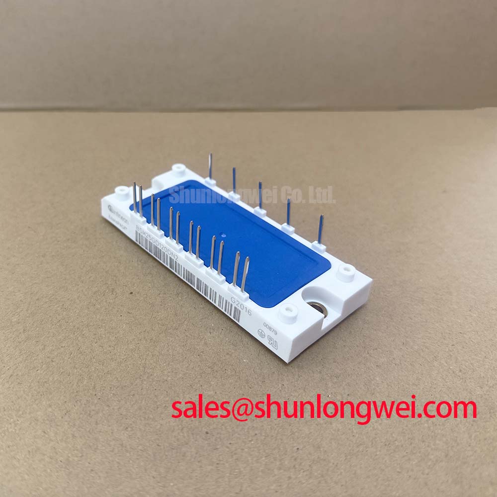

Technical Analysis: Ruggedness by Design
The engineering value of the BSM25GD120DN2 lies in its NPT chip architecture. Unlike modern trench-gate components that prioritize absolute minimum conduction loss, NPT chips offer a wider Reverse Bias Safe Operating Area (RBSOA). This allows the BSM25GD120DN2 to withstand significant voltage spikes and current surges during hard-switching transients, common in heavy-duty industrial power semiconductors applications. For the system designer, this translates to reduced snubber circuit complexity and enhanced long-term reliability.
To understand the thermal efficiency of this module, one can use the analogy of a water pipe. You can think of the junction-to-case thermal resistance ($R_{thJC}$) as the width of a drainage pipe; a lower value means heat—the “water”—can flow away from the silicon die more freely. With a typical $R_{thJC}$ of 0.6 K/W for the IGBT part, the BSM25GD120DN2 ensures that even under high-frequency switching, the internal temperatures remain within safe limits, preventing the thermal runaway often discussed in analyses of IGBT failures.
Optimized Application Scenarios
The BSM25GD120DN2 is a versatile building block for medium-power conversion systems. Its integrated Sixpack topology makes it an ideal fit for the following environments:
- Variable Frequency Drives (VFDs): The 25A rating is perfectly matched for 5.5kW to 7.5kW motor control where high switching frequency and low EMI are required.
- Servo Drive Systems: Precision motion control benefits from the module’s predictable switching behavior and low gate charge.
- Industrial UPS: Reliability during mains-to-battery transitions is bolstered by the 10µs short-circuit withstand time.
- Solar Inverters: High-efficiency DC-AC conversion is achieved by utilizing the module’s fast-recovery freewheeling diodes.
Best Match: Ideal for 400V AC grid-connected industrial drives requiring a balance of robust over-current protection and standardized EconoPack footprint compatibility.
BSM25GD120DN2 Key Specifications
| Parameter Group | Feature | Value |
|---|---|---|
| Absolute Maximums | Collector-Emitter Voltage ($V_{CES}$) | 1200 V |
| Continuous DC Collector Current ($I_C$) | 25 A (@ $T_c=80^circ C$) | |
| Repetitive Peak Collector Current ($I_{CRM}$) | 50 A | |
| Electrical Characteristics | Gate Threshold Voltage ($V_{GE(th)}$) | 4.5 V to 6.5 V |
| Saturation Voltage ($V_{CE(sat)}$) | 2.5 V (typ) | |
| Thermal Properties | IGBT Thermal Resistance ($R_{thJC}$) | 0.6 K/W |
| Operating Junction Temperature ($T_{vj}$) | -40 to +150 °C |
Engineer FAQ: BSM25GD120DN2 Implementation
Q1: What is the recommended gate resistor ($R_G$) for the BSM25GD120DN2 to balance switching losses and EMI?
A: Based on the datasheet, a typical $R_{G(on/off)}$ of 47Ω is recommended. However, for faster transitions, this can be reduced, provided the peak voltage does not exceed $V_{CES}$. For more detail, see our guide on gate resistor selection strategies.
Q2: Can the BSM25GD120DN2 be used in paralleling configurations?
A: Yes. Its NPT technology features a positive temperature coefficient of the collector-emitter saturation voltage. This naturally promotes current sharing between paralleled modules as the warmer chip increases its resistance, redirecting current to cooler chips.
Q3: How should the mounting torque be managed for this EconoPack housing?
A: Proper mechanical installation is critical for thermal performance. The datasheet specifies a mounting torque ($M$) of 3.0 to 6.0 Nm. Under-tightening leads to high thermal resistance, while over-tightening can crack the internal ceramic substrate.
The BSM25GD120DN2 stands as a definitive choice for engineers who prioritize proven NPT reliability and high switching ruggedness. By integrating a complete three-phase inverter into the industry-standard EconoPack footprint, it enables high-efficiency power conversion while simplifying the mechanical and thermal design of next-generation industrial drives.