Mitsubishi CM200DY-24A IGBT Module: High-Efficiency 1200V 200A Dual Switch with CSTBT™ Technology
Mitsubishi CM200DY-24A IGBT Module | 1200V 200A Dual Switch
Optimizing Efficiency with Mitsubishi CSTBT™ Technology
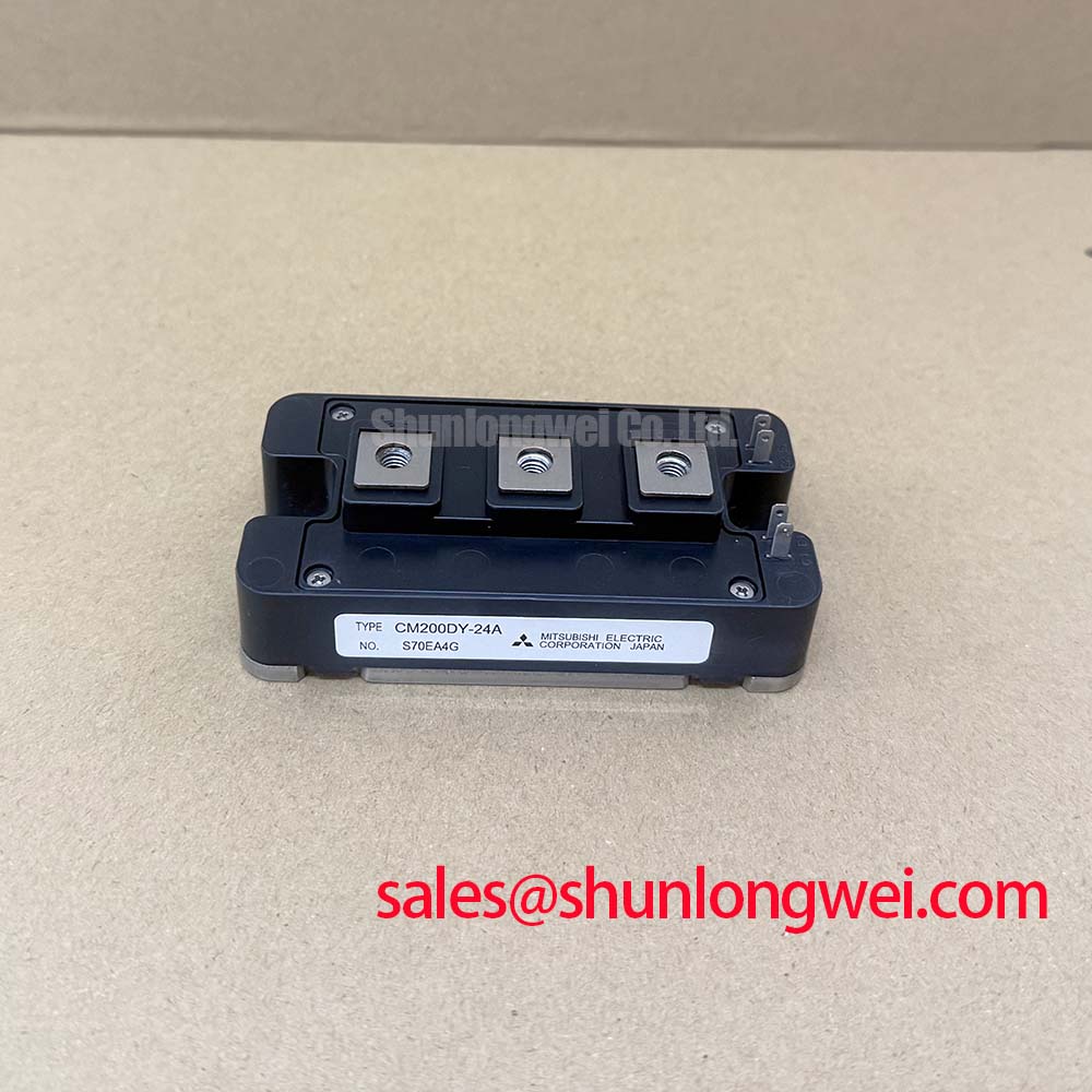
The Mitsubishi CM200DY-24A is an A-Series dual IGBT module engineered to bridge the gap between high current density and thermal stability in medium-power industrial applications. Utilizing advanced CSTBT™ (Carrier Stored Trench-gate Bipolar Transistor) technology, this module minimizes conduction losses while maintaining robust switching performance. For engineers asking about switching efficiency, the CM200DY-24A provides a significant reduction in saturation voltage compared to previous generations, directly improving overall system efficacy in power conversion.
- Core Specifications: 1200V | 200A | $V_{CE(sat)}$ 1.8V (Typ. at $T_j=125^circ C$)
- Key Advantage 1: Reduced conduction losses through optimized carrier distribution.
- Key Advantage 2: Enhanced thermal cycling reliability due to an isolated baseplate design.
Download Official Datasheet (PDF)

Technical Analysis: CSTBT™ and Thermal Dynamics
The engineering core of the CM200DY-24A lies in its CSTBT™ architecture. This technology optimizes the storage of charge carriers near the emitter side of the trench gate, which lowers the on-state voltage drop without compromising the breakdown voltage. In a typical trench gate evolution, achieving a $V_{CE(sat)}$ as low as 1.8V at rated current is essential for reducing the sizing of heat sinks in confined industrial cabinets.
Consider the module’s thermal resistance ($R_{th(j-c)}$) as the width of a drainage pipe; a lower value indicates that heat can flow away from the silicon junction more effectively. With a junction-to-case thermal resistance of 0.11 K/W for the IGBT part, the CM200DY-24A ensures that even under heavy loads, the junction temperature ($T_j$) remains within safe limits. This thermal resilience is critical for preventing common IGBT failures related to overheating and power cycling fatigue.


Optimized Application Scenarios
The CM200DY-24A is a versatile building block for several high-demand power systems:
- AC Motor Drives (VFDs): The dual configuration allows for seamless integration into three-phase inverter bridges, where low $V_{CE(sat)}$ reduces energy waste during continuous operation.
- Solar Inverters: High-voltage reliability up to 1200V supports utility-scale string inverters, benefiting from the module’s low parasitic inductance.
- Uninterruptible Power Supplies (UPS): Rapid switching capabilities ensure high-fidelity sine wave reconstruction during power transitions.
- Industrial Welding: Robustness against current surges makes it suitable for high-frequency welding power stages.
Conclusion: This module is a high-performance match for 400-480V AC line systems requiring reliable 200A switching with minimal thermal management overhead.
Key Specifications Table
| Parameter | Condition | Value |
|---|---|---|
| Collector-Emitter Voltage ($V_{CES}$) | $G-E$ Short-Circuited | 1200 V |
| Collector Current ($I_C$) | $DC, T_C = 80^circ C$ | 200 A |
| Max. Junction Temperature ($T_j$) | Continuous Operation | 150 °C |
| Saturation Voltage ($V_{CE(sat)}$) | $I_C = 200A, T_j = 125^circ C$ | 1.8 V (Typ) |
| Isolation Voltage ($V_{isol}$) | $AC 1 min, f=60Hz$ | 2500 Vrms |
| Thermal Resistance ($R_{th(j-c)}$) | Per IGBT Module | 0.11 K/W |
Engineer FAQ
Q: What is the recommended gate resistance ($R_G$) for the CM200DY-24A?
A: While the optimal value depends on the switching frequency and EMI requirements, the datasheet baseline is typically evaluated around 1.6Ω to 16Ω. Higher values reduce EMI but increase switching losses.
Q: Does this module require a negative gate drive voltage?
A: For 1200V systems, a negative gate-emitter bias (typically -15V) is highly recommended to ensure the IGBT stays off during high $dv/dt$ events, preventing parasitic turn-on.
Q: What is the mounting torque specification for the terminals?
A: The recommended mounting torque for the M5 main terminals and M6 mounting holes is 2.5 to 3.5 N•m. Over-tightening can damage the internal ceramic substrate.
Q: How does the Safe Operating Area (SOA) perform under short-circuit conditions?
A: The CM200DY-24A is designed to withstand short circuits for up to 10μs at $V_{CC}=800V$ and $T_j=125^circ C$, ensuring sufficient time for standard protection circuits to engage. Refer to the SOA curves for peak pulse current limits.
The Mitsubishi CM200DY-24A enables designers to achieve high power density by leveraging the intrinsic low-loss characteristics of CSTBT™ technology. By balancing electrical efficiency with superior thermal management, this 1200V/200A dual module remains a reliable standard for robust industrial inverter and drive systems.