PDMB75E6: High-Efficiency 600V 75A 6-in-1 IGBT Module for Industrial Power Systems
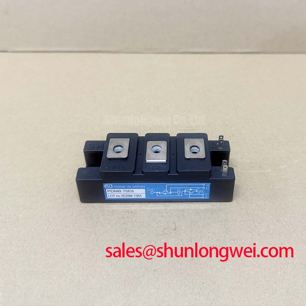
PDMB75E6 Nihon Inter (NIEC) 600V 75A 6-in-1 IGBT Module
Introduction to the High-Integration PDMB75E6 Six-Pack Module
The PDMB75E6 is an industrial-grade, 6-in-1 IGBT (Insulated Gate Bipolar Transistor) power module manufactured by Nihon Inter Electronics Corporation (NIEC, now part of Kyocera). This module is engineered to provide a balanced solution for low-to-medium power conversion tasks, particularly in three-phase inverter topographies. Its unique value proposition (UVP) lies in the synergy between its compact E6 package footprint and an optimized collector-emitter saturation voltage ($V_{CE(sat)}$), which enables high energy efficiency without the typical overhead of complex cooling systems. For engineers asking, “Is the PDMB75E6 suitable for 400V AC systems?”—note that its 600V rating makes it ideal for 200V-230V class AC motor drives and uninterruptible power supplies, providing a robust safety margin against transient voltage spikes.
- Core Specifications: 600V | 75A | $V_{CE(sat)}$ 2.1V (Typical)
- Key Advantage 1: Significant reduction in total power dissipation through low conduction losses.
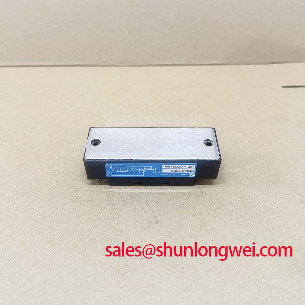
- Key Advantage 2: Isolated baseplate design simplifies mechanical assembly and improves system reliability.
Download Official PDMB75E6 Datasheet (PDF)
Technical Analysis: Efficiency and Thermal Dynamics
The PDMB75E6 utilizes a planar gate structure optimized for a balance between switching speed and durability. In the world of power semiconductors, the saturation voltage ($V_{CESat}$) is a critical parameter. For the PDMB75E6, a typical value of 2.1V at 75A ensures that conduction losses remain manageable during heavy load cycles. This efficiency is further bolstered by the integration of soft-recovery Free Wheeling Diodes (FWD), which mitigate electromagnetic interference (EMI) during high-frequency switching operations.
Thermal management is another cornerstone of this module’s design. To understand the importance of the module’s thermal resistance ($R_{th(j-c)}$), one can imagine thermal resistance as the width of a water pipe. A lower resistance value means heat can “flow” away from the silicon junctions more easily, preventing the device from “overflowing” with heat and failing prematurely. The PDMB75E6 features a low junction-to-case thermal resistance, which, when combined with an integrated NTC thermistor in certain sub-variants, allows for real-time temperature monitoring and proactive protection against thermal runaway.
Optimized Application Scenarios
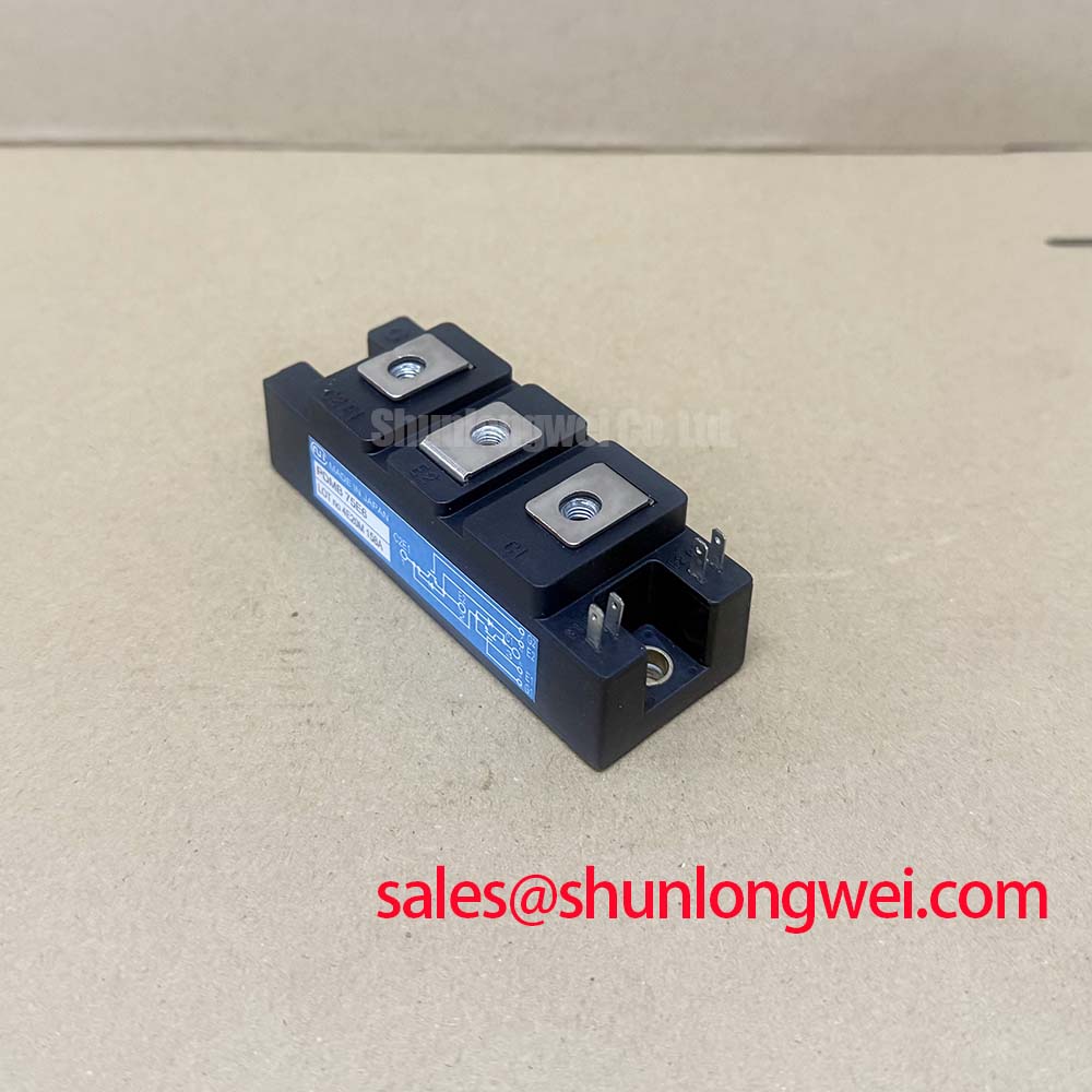
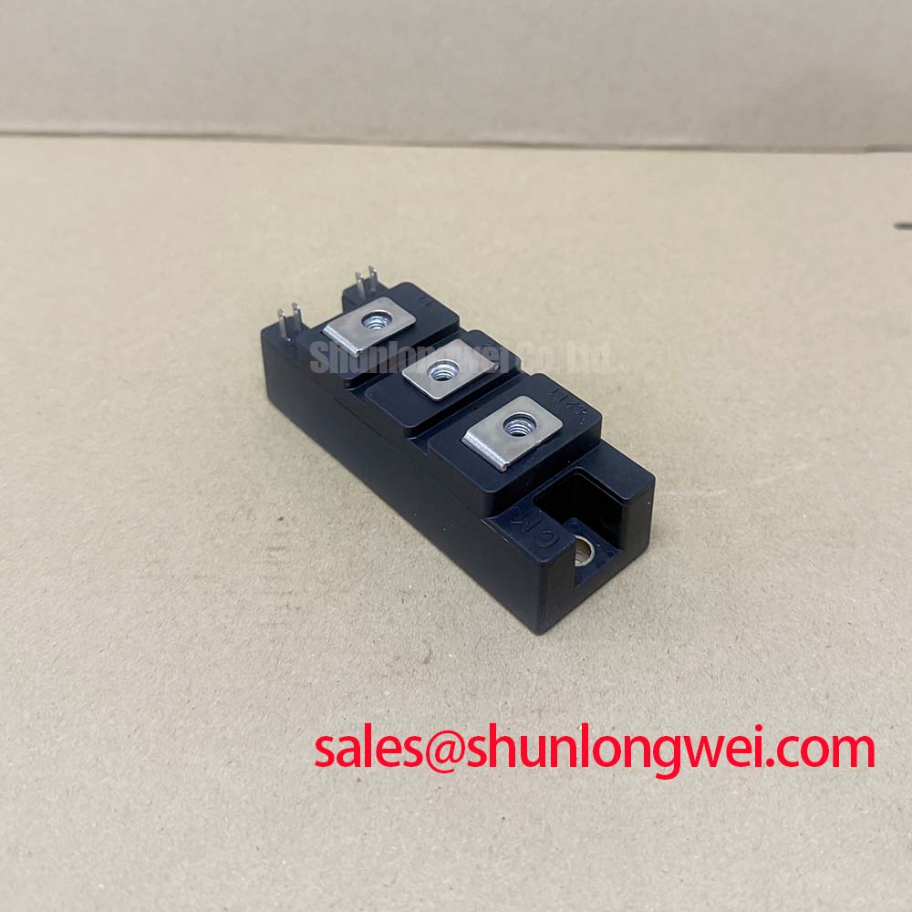
The PDMB75E6 is specifically designed for environments where space is at a premium and reliability cannot be compromised. Its internal configuration as a “Six-Pack” means it contains the three high-side and three low-side switches required for a full three-phase bridge, significantly reducing the impact of parasitic inductance compared to discrete designs.
- Variable Frequency Drives (VFDs): Specifically for 200V class motors where high-current handling and compact integration are required.
- AC Servo Controllers: The low $V_{CE(sat)}$ and soft-recovery diodes support the precision switching needed for motion control.
- Uninterruptible Power Supplies (UPS): High reliability and high-speed switching capabilities ensure seamless power transition.
- Solar Inverters: Effective for residential energy storage systems requiring 600V-rated isolation and efficiency.
Best Match: Systems requiring 75A continuous current in a 200V-230V AC grid environment with strict EMI requirements.

Key Specifications Table
| Parameter Group | Specific Parameter | Value (Typical/Max) |
|---|---|---|
| Absolute Maximum Ratings | Collector-Emitter Voltage ($V_{CES}$) | 600V |
| Continuous Collector Current ($I_C$) | 75A (at $Tc=25^circ C$) | |
| Junction Temperature ($T_j$) | -40 to +150 °C | |
| Electrical Characteristics | Saturation Voltage ($V_{CE(sat)}$) | 2.1V (Typical) |
| Gate-Emitter Threshold ($V_{GE(th)}$) | 5.0V to 8.0V | |
| Thermal Properties | Thermal Resistance (IGBT) | 0.31 °C/W (Max) |
Engineer’s FAQ
Q1: What is the recommended gate voltage for driving the PDMB75E6?
A: According to the datasheet, the gate-emitter threshold voltage ($V_{GE(th)}$) ranges between 5V and 8V. However, for full saturation and to minimize switching losses, a drive voltage of +15V is typically recommended, with a negative bias (e.g., -5V to -15V) to ensure immunity against Miller-effect induced turn-on.
Q2: How does the PDMB75E6 handle short-circuit events?
A: The PDMB75E6 is designed with a specific short-circuit withstand time ($t_{sc}$), typically rated for 10μs under defined conditions. Designers should implement desaturation protection in the gate driver to safely shut down the module within this window.
Q3: Can this module be used in a 480V three-phase system?
A: No. A 480V AC system typically requires IGBTs with a minimum $V_{CES}$ rating of 1200V to handle the peak DC bus voltages (approx. 650V-700V) and switching transients. The 600V rating of the PDMB75E6 is strictly for 200V-240V AC systems. For higher voltage guidance, refer to our thermal design and selection guides.
The PDMB75E6 remains a staple for engineers requiring a high-density, reliable six-pack solution for 600V-class applications. Its proven track record in industrial motor control highlights its capacity to deliver consistent performance through efficient thermal design and optimized electrical characteristics.