Fuji Electric 2MBI200SB120-50 1200V 200A IGBT Module: Technical Analysis and Applications
Fuji Electric 2MBI200SB120-50 1200V 200A IGBT Module
Introduction and Core Highlights
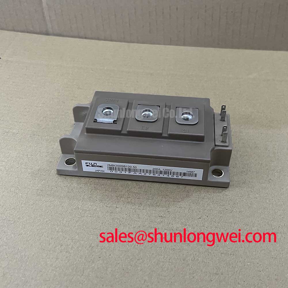
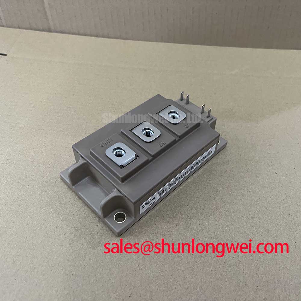
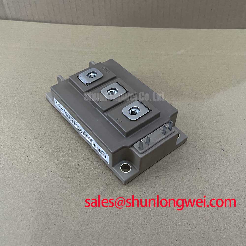
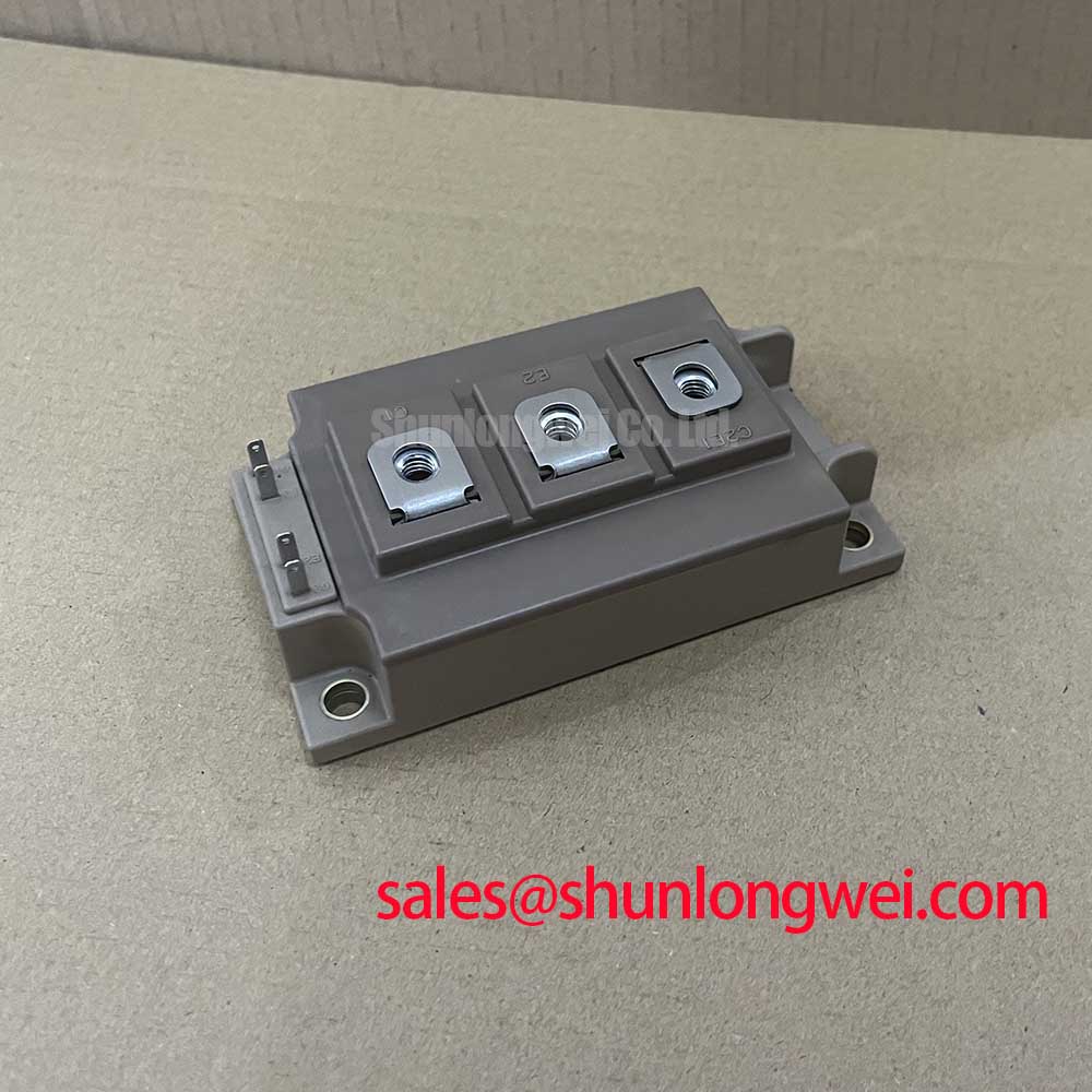
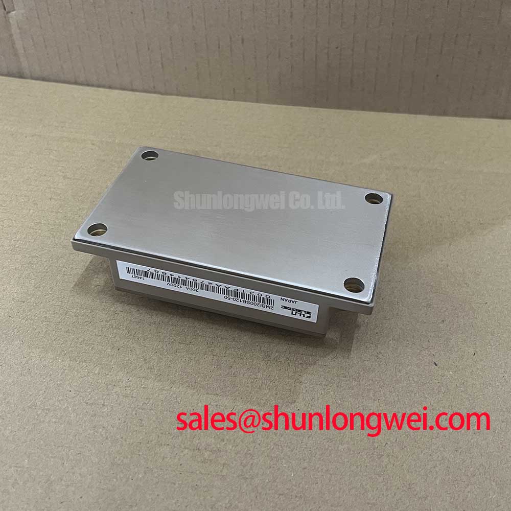
The 2MBI200SB120-50 is a dual channel power semiconductor module housed in an industry-standard package configuration. This module delivers robust switching performance alongside stable transient thermal characteristics. It is designed to handle high current density while minimizing total losses in medium to high power systems.
- Core Specifications: 1200V | 200A | Dual Half-Bridge Configuration
- Engineering Advantages: Optimized thermal transfer pathway, low saturation voltage characteristics.
- Intent Question Answered: Minimizing driving power requirements is achieved through a low overall gate charge. This simplifies gate driver circuit demands while maintaining switching speed.
Download Official Datasheet (PDF)
Technical Analysis of the 2MBI200SB120-50
The device leverages a collector-emitter saturation voltage ($V_{CE(sat)}$) typically rated at 2.3V under full load current. This low value directly influences conduction losses, translating to higher system operating efficiency. Managing this loss ensures the device runs cooler under continuous high-power cycles. The internal freewheeling diode features soft-recovery dynamics, which helps limit electromagnetic interference (EMI) during high $di/dt$ transitions.
To control high junction temperatures, the module features a thermal resistance junction-to-case ($R_{th(j-c)}$) of 0.085°C/W for the IGBT switch. Thermal resistance acts like a narrow pipe in a water system. A lower thermal resistance rating allows heat to clear rapidly from the silicon die to the heatsink. This fast heat transfer prevents thermal bottlenecks that lead to semiconductor degradation and eventual component failures.
Additionally, the 2MBI200SB120-50 maintains switching reliability through a robust safe operating area (SOA). This protective design envelope allows engineers to handle overload transients safely. Understanding the electrical boundaries prevents common high-stress failure modes, protecting the module during short-circuits. Designers must configure gate resistance ($R_G$) appropriately to balance switching speeds and overvoltage spikes.
Industrial Applications
The specifications of this module make it suitable for several high-power industrial installations:
- Variable Frequency Drives (VFDs): The module handles high-current motor control loops and transient overload conditions.
- Uninterruptible Power Supplies (UPS): Fast switching capability ensures reliable power conversion stages under sudden load shifts.
- Solar Inverters: The 1200V rating accommodates wide DC bus voltages for commercial solar arrays.
- Industrial Welding Power Supplies: The robust package design withstands rapid thermal cycling during welding tasks.
Best Match: This module is optimized for industrial inverter systems requiring continuous 200A load execution at voltages up to 1200V.
Key Specifications Table
| Parameter Category | Specification Parameter | Typical Value / Rating |
|---|---|---|
| Absolute Maximum Ratings | Collector-Emitter Voltage ($V_{CES}$) | 1200 V |
| Continuous Collector Current ($I_C$) | 200 A (at $T_C = 80^circ$C) | |
| Pulsed Collector Current ($I_{CP}$) | 400 A (1 ms pulse) | |
| Gate-Emitter Voltage ($V_{GES}$) | ±20 V | |
| Electrical Characteristics | Collector-Emitter Saturation Voltage ($V_{CE(sat)}$) | 2.3 V (typical at $T_j = 25^circ$C, $I_C = 200A$) |
| Gate Threshold Voltage ($V_{GE(th)}$) | 5.5 V to 8.5 V | |
| Turn-on Time ($t_{on}$) | 0.35 µs (typical) | |
| Thermal Characteristics | Thermal Resistance, Junction-to-Case ($R_{th(j-c)}$ IGBT) | 0.085 °C/W (maximum) |
| Thermal Resistance, Junction-to-Case ($R_{th(j-c)}$ Diode) | 0.18 °C/W (maximum) |
Engineer FAQ
Q: What is the isolation rating of the baseplate on the 2MBI200SB120-50?
A: The module isolated copper baseplate is rated to withstand 2500V AC for 1 minute, providing high safety margins in complex industrial environments.
Q: How do turn-off characteristics impact transient voltage spikes?
A: Rapid current changes ($di/dt$) interact with stray inductance to generate collector voltage spikes. Designers should optimize snubber circuits to prevent exceeding the 1200V rating.
Q: What gate resistance range is recommended for standard applications?
A: Refer to the datasheet curves to determine the optimum gate resistance value. This controls the switching time while avoiding excessive switching power loss.
Design Integration Context
Integrating the 2MBI200SB120-50 into power topologies requires careful thermal layout and gate-drive design. Utilizing optimized driving techniques prevents high transient stresses, minimizing the risk of semiconductor degradation. Proper design checks protect against switching failures, supporting stable system performance.