Based on the information provided, the MG75Q1ZS50 is a dual IGBT module in a half-bridge configuration and is a “fundamental building block” for three-phase inverters for VFDs. How many of these modules would be required to build a complete three-phase inverter?
Toshiba MG75Q1ZS50 1200V 75A Dual IGBT Module
High-Reliability Power Switching with Integrated Half-Bridge
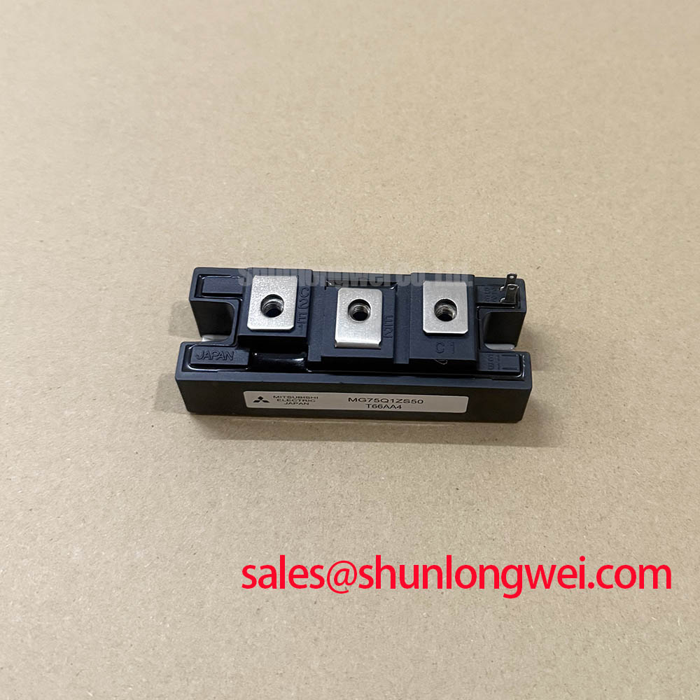
The Toshiba MG75Q1ZS50 is a robust Silicon N Channel IGBT module engineered for high-power switching applications. It integrates two IGBTs in a half-bridge configuration, providing a compact and efficient solution for motor control and inverter designs. With a high collector-emitter voltage of 1200V and a continuous collector current rating of 75A, this module offers a solid foundation for demanding industrial systems. Key advantages include a high isolation voltage and a streamlined package that simplifies both mechanical mounting and electrical layout.
- Core Specifications: 1200V | 75A | VCE(sat) 3.6V (Max)
- Key Advantages: High electrical isolation enhances system safety, and the integrated half-bridge reduces component count.
This module is well-suited for engineers developing three-phase inverters for Variable Frequency Drives (VFDs), as its dual-device structure is a fundamental building block for such topologies.
Download the Official MG75Q1ZS50 Datasheet (PDF)

Technical Analysis for System Integration
A critical parameter for ensuring operational safety and reliability is the module’s isolation voltage (Visol), rated at 2500V AC for one minute. This high isolation capability acts like a robust safety barrier between the high-power switching circuit and the low-voltage control logic. It is essential for preventing catastrophic failures where high voltage could damage sensitive microcontrollers or pose a risk to operators. This feature is particularly important in industrial environments where electrical noise and potential fault conditions are prevalent.
The MG75Q1ZS50’s internal half-bridge circuit, which includes both the IGBTs and co-packaged free-wheeling diodes, offers significant design advantages over discrete components. This integration minimizes the physical loop area for current, thereby reducing parasitic inductance. Lower inductance is crucial for mitigating voltage overshoots during high-speed switching events, which can be further managed with a proper gate drive design. This streamlined approach simplifies PCB layout, reduces assembly complexity, and contributes to more predictable switching performance.


Optimized Application Scenarios
The electrical and mechanical characteristics of the MG75Q1ZS50 make it a strong candidate for several high-power applications:
- Motor Controls: The 1200V rating provides a substantial safety margin for 400/480V AC motor drive inverters, and the 75A current capacity is suitable for controlling industrial motors of several kilowatts.
- Uninterruptible Power Supplies (UPS): Its robust isolation and power handling are ideal for the inverter stage of online UPS systems, ensuring reliable power conversion.
- Welding Power Supplies: The module can effectively handle the pulsed, high-current demands inherent to switching power sources for welding equipment.
- High-Power SMPS: It serves as an efficient switch in chopper and booster circuits for large-scale switch-mode power supplies.
This module is an optimal match for industrial applications requiring a reliable, integrated 1200V half-bridge power stage with high electrical isolation.
Key Specifications of the MG75Q1ZS50
| Parameter | Value | |
|---|---|---|
| Absolute Maximum Ratings (Ta = 25°C) | Collector-Emitter Voltage (VCES) | 1200V |
| Collector Current (IC) | 75A | |
| Isolation Voltage (Visol) | 2500V (AC, 1 min) | |
| Electrical Characteristics (Tj = 25°C unless noted) | Collector-Emitter Saturation Voltage (VCE(sat)) @ IC=75A, VGE=15V | 3.6V (Max) |
| Fall Time (tf) @ Inductive Load | 0.3µs (Max) | |
| Diode Forward Voltage (VF) @ IF=75A | 3.5V (Max) | |
| Gate-Emitter Cut-off Voltage (VGE(off)) | 3.0V (Min) to 6.0V (Max) | |
| Thermal Characteristics | Thermal Resistance (Rth(j-c)) – Transistor | 0.2°C/W |
| Thermal Resistance (Rth(j-c)) – Diode | 0.47°C/W | |
Engineer’s FAQ
1. What are the key considerations when designing a heatsink for the MG75Q1ZS50?
To design an effective heatsink, you must use the thermal resistance from junction to case (Rth(j-c)). The datasheet specifies this as 0.2°C/W for the transistor and 0.47°C/W for the diode. Calculate the total power dissipation and use this value to select a heatsink with an appropriate thermal resistance (case-to-ambient) to keep the junction temperature below the maximum rating of 150°C under worst-case operating conditions.
2. What is the recommended mounting torque for this module?
The datasheet’s mechanical drawing specifies the torque for the main terminal screws (M5) and the mounting screws (M6). Adhering to these torque specifications is crucial for ensuring both reliable electrical contact and optimal thermal transfer to the heatsink. Refer to the official datasheet for the exact torque values to prevent damage to the module.
3. Does the MG75Q1ZS50 include an integrated gate driver?
No, the MG75Q1ZS50 is a standard GTR (Giant Transistor) module and does not contain an integrated gate driver or protection circuits. An external gate driver circuit is required to provide the specified gate-emitter voltage (typically +15V/-15V) to ensure proper switching behavior. For more information on this topic, consult our guide on the advantages of integrated power modules (IPMs).
4. Can this module be used in parallel to achieve higher current?
While paralleling IGBT modules is possible, it requires careful design to ensure proper current sharing. Factors like VCE(sat) matching, gate drive symmetry, and minimizing inductance in the busbar layout are critical. The datasheet for the MG75Q1ZS50 does not provide specific guidance on paralleling, so engineers should perform thorough testing to validate performance in such a configuration.
Enabling Robust Power Conversion
The MG75Q1ZS50 provides a dependable and electrically isolated power switching foundation. Its integrated half-bridge design enables engineers to develop efficient and compact motor drives and inverters, simplifying thermal management and system layout while maintaining high operational safety standards in industrial power systems.