“Design and manufacture a wireless transceiver that performs mixed transmission of digital-analog signals on the same channel. Among them, the digital signal is composed of a set of 4 numbers from 0 to 9; the analog signal is a voice signal with a frequency range of 100 Hz to 5 kHz. Using wireless transmission, the carrier frequency range is 20~30MHz, the channel bandwidth is not more than 25kHz, and the shortest transmission distance between the transceiver equipment is not less than 100cm.
“
This year’s college student electronic competition has ended, the following is an analysis of the E questions.
1. Task
Design and manufacture a wireless transceiver that performs mixed transmission of digital-analog signals on the same channel. Among them, the digital signal is composed of a set of 4 numbers from 0 to 9; the analog signal is a voice signal with a frequency range of 100 Hz to 5 kHz. Using wireless transmission, the carrier frequency range is 20~30MHz, the channel bandwidth is not more than 25kHz, and the shortest transmission distance between the transceiver equipment is not less than 100cm.
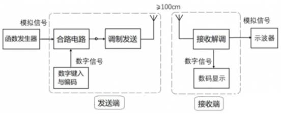
The transmitting end of the transceiver completes the combined processing of the digital signal and the analog signal, and modulates and transmits on the same channel.
The receiving end of the transceiver completes receiving and demodulating, and separates the digital signal and the analog signal. The digital signal is displayed with a digital tube, and the analog signal is observed with an oscilloscope.

2. Requirements
1. Basic requirements
(1) Realize analog signal transmission. The analog signal is a voice signal of 100 Hz to 5 kHz, and the demodulated analog signal waveform at the receiving end is required to have no obvious distortion. When only analog signals are being transmitted, the digital display on the receiving end is off.
(2) Realize digital signal transmission. First type in a group of 4 numbers from 0 to 9 and store and display them on the sending end, and then press the send button to continuously and cyclically transmit the digital signal. The digital signal is demodulated at the receiving end and displayed through 4 digital tubes. The response time required to start sending to the digital tube display is not more than 2 seconds. When the sender presses the stop button, the digital signal transmission is ended, and at the same time, the display of the transmitted numbers is cleared on the sender, and new numbers are waited for input.
(3) Realize the mixed transmission of digital-analog signals. Enter a group of numbers arbitrarily, mix and modulate with analog signals for transmission. The receiving end is required to be able to demodulate the digital signal and the analog signal correctly, the digital display is correct, and the analog signal waveform has no obvious distortion.
(4) The channel bandwidth of the transceiver is not more than 25kHz, and the carrier frequency range is 20~30MHz. It is required that the transceiver can be selected and set in no less than 3 carrier frequencies, and the specific carrier frequency is determined by itself.
2. Play part
(1) After the digital signal transmission is stopped at the transmitting end, the digital display at the receiving end will automatically go out after a 5 second delay.
(2) On the premise of meeting the basic requirements, the lower the power consumption of the transceiver, the better.
(3) On the premise of meeting the basic requirements, the frequency range of the analog signal transmitted by the transceiver is extended to 50Hz~10kHz.
(4) Others.
Three, description
(1) The digital and analog signals must be processed by the combined circuit first, and then modulated and transmitted on the same channel. The modulation method and modulation degree are determined by themselves. There should be an observation port at the output end of the combined circuit for the oscilloscope to observe the waveform changes of the combined signal.
(2) There must not be any connection between the transmitter and receiver of the transceiver.
(3) The transmitting end of the transceiver and the antenna are connected by SMA plugs, the transmitting end is F (female) head, and the antenna end is M (male) head. The length of the antenna does not exceed 1 meter.
(4) Both the transmitting end and the receiving end of the transceiver are powered by a single battery power supply, and the power supply circuit at the transmitting end should have a test port for supply voltage and current.
(5) The carrier frequency of the transceiver should be selected as far as possible to avoid environmental radio wave interference.
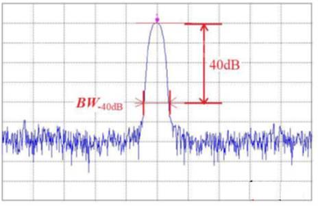
(6) The channel bandwidth in this topic is agreed to be the -40dB bandwidth of the modulated signal, which is measured by a spectrum analyzer. The details are shown in the figure below.


Topic analysis and project design
This topic is a relatively complete wireless transceiver system that requires simultaneous transmission of analog and digital signals.
According to the description of the analog signal transmission requirements in the title, the analog signal adopts the analog transmission method. The frequency range of the analog signal that needs to be transmitted is 50 Hz to 10 kHz. If AM modulation is used, the required channel bandwidth is 20 kHz.
The digital signal that needs to be transmitted is a 4-digit decimal number, plus redundant information such as the synchronization header and check code of the data frame, the number of bits that need to be transmitted should not exceed 40. The title also stipulates that the time from the beginning of the transmission to the terminal display should not exceed 2 seconds, so the actual transmission bit rate can be as low as 20bps. According to Shannon’s theorem, as long as the signal-to-noise ratio of the channel is not extremely bad, the channel bandwidth required for data transmission is extremely narrow, which is almost negligible compared with analog signals.
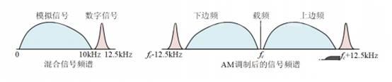
The channel bandwidth specified by the title is 25kHz, the analog signal occupies the middle 20kHz, and the bandwidth of 2.5kHz is left on both sides, and the above-mentioned digital channel is more than enough. Therefore, you can select a subcarrier frequency between 10kHz~12.5kHz (for example, 11.2kHz, which is the geometric average of 10kHz and 12.5kHz), and modulate this subcarrier with a digital signal to obtain a digital modulated signal (the simplest modulation method is OOK modulation).
Finally, the digital modulated signal and the analog signal are superimposed, and the superimposed mixed signal is modulated with AM modulation on the carrier, amplified and then sent to the antenna for transmission. The overall spectrum structure is as follows:


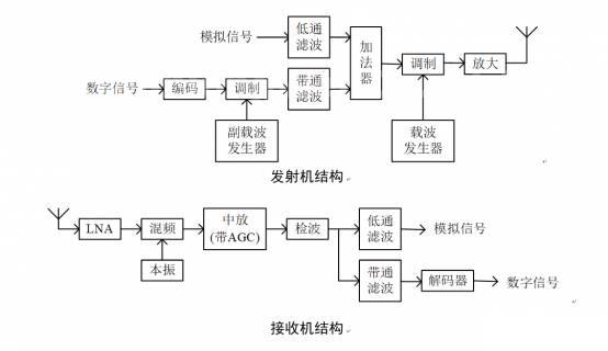
The circuit structure of this scheme is shown in the figure below.


In this scheme, the filter that distinguishes the two signals is the key.
The requirement of the low-pass filter of the analog signal is: there is a sufficiently large amount of attenuation near the sub-carrier frequency of the digital signal, and the attenuation at 12.5kHz should be greater than 40dB. According to these two requirements, it is a better choice to use a high-order elliptic filter and design the first zero frequency of the filter near the subcarrier frequency of the digital signal. For example, using a 7th-order elliptical low-pass filter with an in-band fluctuation of 0.5dB, the attenuation at 11.2kHz (digital subcarrier frequency) and greater than 12.5kHz can be greater than 45dB.
The requirement of the band-pass filter of the digital signal is: there should be enough attenuation at 10kHz and 12.5kHz. Because the bandwidth of the digital signal is extremely low, cascading multiple point-pass filters is the simplest method. For example, if three point-pass filters with a center frequency of 11.2kHz and a Q value of 25 are cascaded, their total bandwidth is about 20Hz, and the attenuation at 10kHz and 12.5kHz is about 45dB.
The receiving part is a typical superheterodyne receiver structure, in which the analog signal reception is basically the same as that of an ordinary AM receiver.
The intermediate amplifier circuit should have an AGC function to ensure that the amplitude of the output signal does not change much when the receiving conditions change, so as to facilitate subsequent digital signal demodulation.
The decoder structure of the digital receiving part varies with the modulation method. If it is OOK modulation, the signal amplitude after the band-pass filter is the 1 and 0 of the baseband signal, and it can be sent to the microprocessor for decoding as long as it is reshaped by the comparator. If it is another modulation method, it may be necessary to restore the subcarrier as a synchronization signal before performing synchronization decoding.
Obviously, for the situation where the bandwidth of the two signals of this topic is wide and the other is narrow, as long as the spectrum is arranged reasonably, the above-mentioned hybrid transmission scheme is effective and the circuit is relatively simple. From the given parameters and basic requirements 1, description 1, and other conditions, it can be guessed that the proposition seems to be based on this mixed transmission scheme.
This year’s college student electronic competition has ended, the following is an analysis of the E questions.
1. Task
Design and manufacture a wireless transceiver that performs mixed transmission of digital-analog signals on the same channel. Among them, the digital signal is composed of a set of 4 numbers from 0 to 9; the analog signal is a voice signal with a frequency range of 100 Hz to 5 kHz. Using wireless transmission, the carrier frequency range is 20~30MHz, the channel bandwidth is not more than 25kHz, and the shortest transmission distance between the transceiver equipment is not less than 100cm.
The transmitting end of the transceiver completes the combined processing of the digital signal and the analog signal, and modulates and transmits on the same channel.
The receiving end of the transceiver completes receiving and demodulating, and separates the digital signal and the analog signal. The digital signal is displayed with a digital tube, and the analog signal is observed with an oscilloscope.

2. Requirements
1. Basic requirements
(1) Realize analog signal transmission. The analog signal is a voice signal of 100 Hz to 5 kHz, and the demodulated analog signal waveform at the receiving end is required to have no obvious distortion. When only analog signals are being transmitted, the digital display on the receiving end is off.
(2) Realize digital signal transmission. First type in a group of 4 numbers from 0 to 9 and store and display them on the sending end, and then press the send button to continuously and cyclically transmit the digital signal. The digital signal is demodulated at the receiving end and displayed through 4 digital tubes. The response time required to start sending to the digital tube display is not more than 2 seconds. When the sender presses the stop button, the digital signal transmission is ended, and at the same time, the display of the transmitted numbers is cleared on the sender, and new numbers are waited for input.
(3) Realize the mixed transmission of digital-analog signals. Enter a group of numbers arbitrarily, mix and modulate with analog signals for transmission. The receiving end is required to be able to demodulate the digital signal and the analog signal correctly, the digital display is correct, and the analog signal waveform has no obvious distortion.
(4) The channel bandwidth of the transceiver is not more than 25kHz, and the carrier frequency range is 20~30MHz. It is required that the transceiver can be selected and set in no less than 3 carrier frequencies, and the specific carrier frequency is determined by itself.
2. Play part
(1) After the digital signal transmission is stopped at the transmitting end, the digital display at the receiving end will automatically go out after a 5 second delay.
(2) On the premise of meeting the basic requirements, the lower the power consumption of the transceiver, the better.
(3) On the premise of meeting the basic requirements, the frequency range of the analog signal transmitted by the transceiver is extended to 50Hz~10kHz.
(4) Others.
Three, description
(1) The digital and analog signals must be processed by the combined circuit first, and then modulated and transmitted on the same channel. The modulation method and modulation degree are determined by themselves. There should be an observation port at the output end of the combined circuit for the oscilloscope to observe the waveform changes of the combined signal.
(2) There must not be any connection between the transmitter and receiver of the transceiver.
(3) The transmitting end of the transceiver and the antenna are connected by SMA plugs, the transmitting end is F (female) head, and the antenna end is M (male) head. The length of the antenna does not exceed 1 meter.
(4) Both the transmitting end and the receiving end of the transceiver are powered by a single battery power supply, and the power supply circuit at the transmitting end should have a test port for supply voltage and current.
(5) The carrier frequency of the transceiver should be selected as far as possible to avoid environmental radio wave interference.
(6) The channel bandwidth in this topic is agreed to be the -40dB bandwidth of the modulated signal, which is measured by a spectrum analyzer. The details are shown in the figure below.
Topic analysis and project design
This topic is a relatively complete wireless transceiver system that requires simultaneous transmission of analog and digital signals.
According to the description of the analog signal transmission requirements in the title, the analog signal adopts the analog transmission method. The frequency range of the analog signal that needs to be transmitted is 50 Hz to 10 kHz. If AM modulation is used, the required channel bandwidth is 20 kHz.
The digital signal that needs to be transmitted is a 4-digit decimal number, plus redundant information such as the synchronization header and check code of the data frame, the number of bits that need to be transmitted should not exceed 40. The title also stipulates that the time from the beginning of the transmission to the terminal display should not exceed 2 seconds, so the actual transmission bit rate can be as low as 20bps. According to Shannon’s theorem, as long as the signal-to-noise ratio of the channel is not extremely bad, the channel bandwidth required for data transmission is extremely narrow, which is almost negligible compared with analog signals.
The channel bandwidth specified by the title is 25kHz, the analog signal occupies the middle 20kHz, and the bandwidth of 2.5kHz is left on both sides, and the above-mentioned digital channel is more than enough. Therefore, you can select a subcarrier frequency between 10kHz~12.5kHz (for example, 11.2kHz, which is the geometric average of 10kHz and 12.5kHz), and modulate this subcarrier with a digital signal to obtain a digital modulated signal (the simplest modulation method is OOK modulation).
Finally, the digital modulated signal and the analog signal are superimposed, and the superimposed mixed signal is modulated with AM modulation on the carrier, amplified and then sent to the antenna for transmission. The overall spectrum structure is as follows:
The circuit structure of this scheme is shown in the figure below.
In this scheme, the filter that distinguishes the two signals is the key.
The requirement of the low-pass filter of the analog signal is: there is a sufficiently large amount of attenuation near the sub-carrier frequency of the digital signal, and the attenuation at 12.5kHz should be greater than 40dB. According to these two requirements, it is a better choice to use a high-order elliptic filter and design the first zero frequency of the filter near the subcarrier frequency of the digital signal. For example, using a 7th-order elliptical low-pass filter with an in-band fluctuation of 0.5dB, the attenuation at 11.2kHz (digital subcarrier frequency) and greater than 12.5kHz can be greater than 45dB.
The requirement of the band pass filter of the digital signal is: There should be enough attenuation at 10kHz and 12.5kHz. Because the bandwidth of the digital signal is extremely low, cascading multiple point-pass filters is the simplest method. For example, if three point-pass filters with a center frequency of 11.2kHz and a Q value of 25 are cascaded, their total bandwidth is about 20Hz, and the attenuation at 10kHz and 12.5kHz is about 45dB.
The receiving part is a typical superheterodyne receiver structure, in which the analog signal reception is basically the same as that of an ordinary AM receiver.
The intermediate amplifier circuit should have an AGC function to ensure that the amplitude of the output signal does not change much when the receiving conditions change, so as to facilitate subsequent digital signal demodulation.
The decoder structure of the digital receiving part varies with the modulation method. If it is OOK modulation, the signal amplitude after the band-pass filter is the 1 and 0 of the baseband signal, and it can be sent to the microprocessor for decoding as long as it is reshaped by the comparator. If it is another modulation method, it may be necessary to restore the subcarrier as a synchronization signal before performing synchronization decoding.
Obviously, for the situation where the bandwidth of the two signals of this topic is wide and the other is narrow, as long as the spectrum is arranged reasonably, the above-mentioned hybrid transmission scheme is effective and the circuit is relatively simple. From the given parameters and basic requirements 1, description 1, and other conditions, it can be guessed that the proposition seems to be based on this mixed transmission scheme.
The Links: SKIIP39GA12T4V1 CM600DU-5F