“In actual industrial, electric power, automation and instrumentation applications, the RS-485 bus standard is one of the widely used physical layer bus design standards. Since it will work in harsh electromagnetic environments, in order to ensure that these data ports can be installed in the final To work properly in the environment, they must comply with relevant electromagnetic compatibility (EMC) regulations. From the principle to the actual measurement, we will bring you a detailed analysis of the port protection of RS485.
“
In actual industrial, electric power, automation and instrumentation applications, the RS-485 bus standard is one of the widely used physical layer bus design standards. Since it will work in harsh electromagnetic environments, in order to ensure that these data ports can be installed in the final To work properly in the environment, they must comply with relevant electromagnetic compatibility (EMC) regulations. From the principle to the actual measurement, we will bring you a detailed analysis of the port protection of RS485.
In the EMC design of the RS-485 port, we need to focus on three factors: electrostatic discharge (ESD), electrical fast transient (EFT) and surge (Surge). The International Electrotechnical Commission (IEC) specifications define a set of EMC immunity requirements. This set of specifications includes the following three types of high-voltage transients that designers need to ensure that data communication lines are not damaged by these transients.
The three types are:
IEC 61000-4-2 Electrostatic Discharge (ESD)
IEC 61000-4-4 Electrical Fast Transients (EFT)
IEC 61000-4-5 Surge Immunity (Surge)
electrostatic discharge
Electrostatic discharge (ESD) refers to the sudden transmission of electrostatic charge between two charged objects with different potentials due to close contact or conduction of electric field. Its characteristic is that there is a larger current in a shorter time. The main purpose of the IEC 61000-4-2 test is to determine the immunity of the system to external ESD events of the system during the working process. IEC 61000-4-2 specifies the voltage test levels under different environmental conditions, which are divided into 4 levels. Grade 1 mild, grade 4 severe. Classes 1 and 2 are suitable for products installed in controlled environments with anti-static materials. Levels 3 and 4 are for products installed in more severe environments where ESD events with higher voltages are more common.
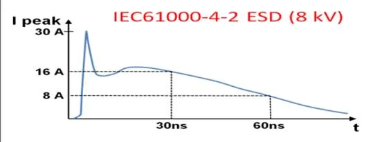
Figure 1: ESD characteristic curve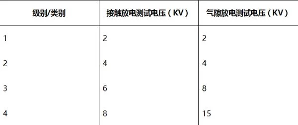
Figure 2: IEC 61000-4-2 ESD test levels and installation categories


Electrical fast transients (bursts)
Electrical fast transients (EFT) test the coupling of large numbers of extremely fast transient pulses onto signal lines, the transient disturbances associated with systems and external switching circuits that can be capacitively coupled to communication ports. EFT windups include Relay and switch contact bounce, or transients due to inductive or capacitive load switching, all of which are common in industrial environments. The EFT test defined in EC 61000-4-4 is to simulate the interference generated by these events.
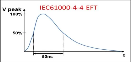
Figure 3: EFT characteristic curve

IEC 61000-4-4 specifies the voltage test levels under different environmental conditions, which are divided into 4 levels. At the same time, the test voltage and pulse repetition rate corresponding to different test levels are specified.
• Level 1 indicates a well protected environment
• Class 2 indicates a protected environment
• Class 3 indicates a typical industrial environment
• Class 4 for harsh industrial environments
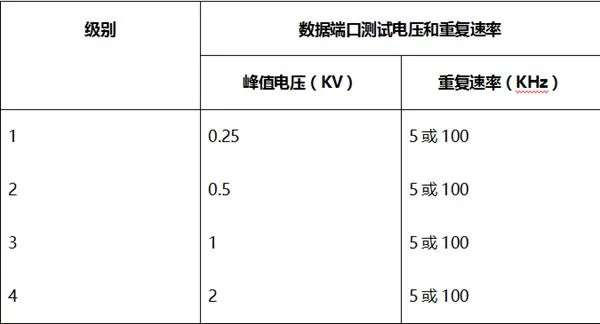
Figure 4: IEC 61000-4-4 EFT test levels

Surge
Surges are usually caused by overvoltage conditions caused by switching operations or by lightning strikes. Switching transients can be caused by power system switching, load changes in the power distribution system, or various system faults. Lightning transients can be caused by nearby lightning strikes causing large currents and voltages to be injected into the circuit. IEC 61000-4-5 defines waveforms, test methods and test levels for evaluating the immunity of electrical and Electronic equipment when susceptible to these surge phenomena.
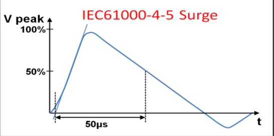
Figure 5: Surge characteristic curve

The energy level of the surge can be three to four orders of magnitude that of an ESD or EFT pulse energy level. Therefore, surges can be considered as a serious category in the EMC transient specification. Because of the similarities between ESD and EFT, the corresponding circuit protection designs are also similar, but due to the high energy of the surge, it must be handled differently.
Angus Zhao, Deputy Director of Technical Support Department of Excelpoint Shijian Company, said: “The process of developing EMC protection circuits is to meet the corresponding requirements of the above three kinds of transient immunity specifications according to the actual application scenarios, while ensuring the cost. Benefits. This seemingly complicated work actually has its own principles and routines to follow.”
The corresponding standard requirements of the RS-485 port EMC solution are actually the goals to be achieved by the protection circuit design. In order to achieve such a goal, it has its own design principles:
There are two main ways to provide protection against transients: overcurrent protection is used to limit peak current; overvoltage protection is used to limit peak voltage. A typical protection scheme design includes primary protection and secondary protection. Primary protection diverts most of the transient energy away from the system and is usually located at the interface between the system and the environment where it diverts the transient to earth, thereby removing most of the energy. The purpose of secondary protection is to protect the various components of the system from any transient voltages and currents that the primary protection allows. Secondary protection is usually more focused on specific components of the system being protected. It is optimized to ensure protection against these residual transients while still allowing these sensitive parts of the system to function properly. Angus Zhao, deputy director of Excelpoint Shijian Technical Support Department, said: “These two methods must ensure that the main design and the secondary design can cooperate with the system input/output together to minimize the stress on the protected circuit. At the same time in the design, Generally, there will be a coordination element between the primary protection device and the secondary protection device, such as a Resistor or a nonlinear overcurrent protection device, to ensure coordination.”
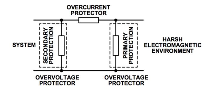
Figure 1: Traditional EMC protection solution architecture

In accordance with the above specification requirements and design principles, we provide three different levels of EMC protection solutions below, all of which have passed the third-party independent EMC compatibility test. The components used in the scheme include:
ADM3485EARZ 3.3 V RS-485 Transceiver (ADI)
TVS Transient Voltage Suppressor CDSOT23-SM712 (Bourns)
TBU Transient Blockout Unit TBU-CA065-200-WH (Bourns)
TIST Thyristor Surge Protector TISP4240M3BJR-S (Bourns)
GDT Gas Discharge Tube 2038-15-SM-RPLF (Bourns)
Option One
EFT and ESD transients have similar energy levels, while surge waveforms have energy levels three to four orders of magnitude higher. Protection against ESD and EFT can be accomplished in a similar manner, while protection solutions for other surges are more complex. This solution provides Level 4 ESD and EFT and Level 2 surge protection.
This solution uses Bourns’ CDSOT23-SM712 TVS array, which includes two bidirectional TVS diodes. TVSs are silicon based devices. Under normal operating conditions, TVS has a high impedance to ground; ideally it is an open circuit. The protection method is to clamp the overvoltage caused by the transient to the voltage limit. This is achieved through the low impedance avalanche breakdown of the PN junction.When a transient voltage greater than the breakdown voltage of the TVS is generated, the TVS will clamp the transient to a predetermined level less than the breakdown voltage of the protection device, simply
It is important to ensure that the breakdown voltage of the TVS is outside the normal operating range of the protected pin. The unique feature of the CDSOT23-SM712 is that it has an asymmetrical breakdown voltage of 13.3 V and C7.5 V, which matches the common-mode range of the transceiver from 12 V to C7 V of the RS-485 chip ADM3485E, thereby providing protection while limiting ground to reduce overvoltage stress on the RS-485 transceiver.
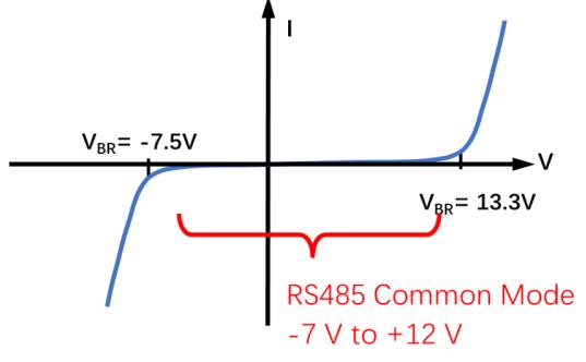
Figure 2: CDSOT23-SM712 TVS characteristic curve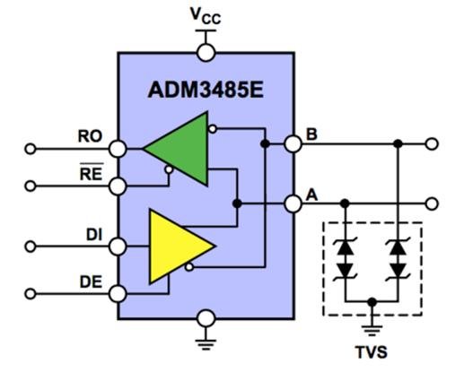
Figure 3: Protection scheme based on TVS array


Option II
If the level of surge protection is to be increased, the protection circuit will become more complicated. In the second scheme, we increase the level of surge protection to level four.
In this scheme, the secondary protection is provided by TVS (CDSOT23-SM712), and the main protection is provided by TISP (TISP4240M3BJR-S). Realized by current protection device TBU (TBU-CA065-200-WH).
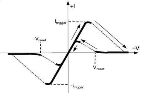
Figure 4: Characteristic curve of TBU

When transient energy is applied to the protection circuit, the TVS will break down, protecting the device by providing a low impedance path to ground. Due to the high voltage and current, the TVS must also be protected by limiting the current passing through it. This can be done using a TBU, an active high-speed overcurrent protection element that blocks current instead of shunting it to ground. As a series element, it responds to the current through the device rather than the voltage across the interface. TBU is a high-speed overcurrent protection device with preset current limit and high voltage withstand capability. When an overcurrent occurs and the TVS breaks down due to a transient event, the current in the TBU will rise to the current limit level set by the device. At this point, the TBU disconnects the protected circuit from the surge in less than 1 μs.During the remainder of the transient, the TBU remains in the protected blocking state with very little current through the protected circuit
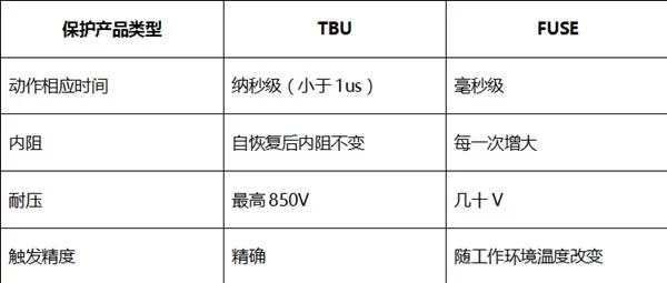
Figure 5: Differences between TBU and PTC (Fuse)

Like all overcurrent protection techniques, the TBU has a breakdown voltage, so the main protection device must clamp the voltage and redirect the transient energy to ground. This is usually achieved using technologies such as gas discharge tubes or solid state discharge tubes (thyristors) TISPs. The TISP acts as the main protection device, and when its predefined protection voltage is exceeded, it provides a transient open low impedance path to ground, diverting most of the transient energy away from the system and other protection devices.
The nonlinear voltage-current characteristic of TISP limits overvoltage by diverting the generated current. As a thyristor, TISP has a discontinuous voltage-current characteristic, which is caused by switching action between high voltage region and low voltage region. Before the TISP device switches to a low-voltage state, it has a low-impedance ground path to shunt the transient energy, and the avalanche breakdown region causes the clamping action.
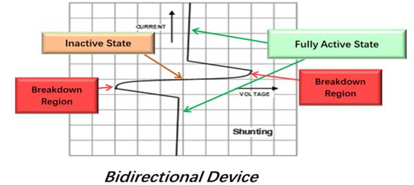
Figure 6: Characteristic curve of TISP

During the process of limiting overvoltage, the protected circuit is briefly exposed to high voltage, so the TISP device is in the breakdown region before switching to the low-voltage protection open state. The TBU will protect the backend circuitry from damage due to the high currents caused by this high voltage. When the diverted current drops below a critical value, the TISP device automatically resets to resume normal system operation.
All three of the above elements work together to provide system level protection for the system against high voltage and high current transients in conjunction with the system input/output.
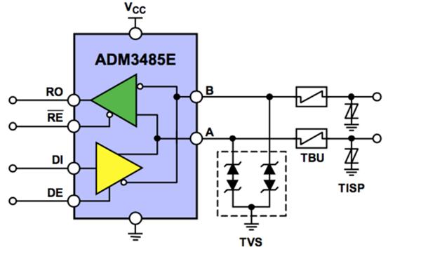
Figure 7: TVS, TBU and TISP work together to provide more protection

third solution
If the protection scheme needs to handle a 6 kV surge transient, some adjustments to the scheme will be required. The new scheme works similarly to protection scheme two; but this circuit uses a gas discharge tube (GDT) instead of a TISP to protect the TBU, thereby protecting the secondary protection device TVS. Compared with TISP, GDT adopts the principle of gas discharge, which can provide protection against greater overvoltage and overcurrent stress. The rated current of TISP is 220 A, and the rated current of GDT is 5 kA (calculated by unit conductor).
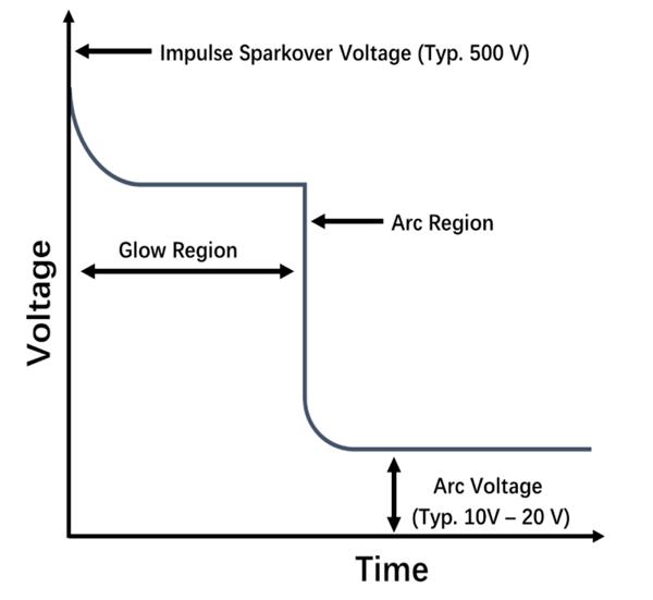
Figure 8: Characteristic curve of GDT

GDTs are primarily used as primary protection devices, providing a low impedance path to ground to protect against overvoltage transients. When the transient voltage reaches the GDT sparkover voltage, the GDT will switch from the high-impedance off state to arcing mode. In arc mode, the GDT acts as a virtual short circuit, providing a transient open-circuit current drain path to ground, diverting transient surge currents away from the protected device.
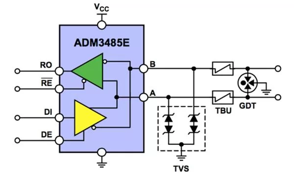
Figure 9: Using TVS, TBU, and GDT to work together can withstand greater overvoltage and overcurrent stress

Angus Zhao, deputy director of the technical support department of Excelpoint Shijian Company, concluded: the EMC solution for RS-485 port has its own routine, and it is not difficult to make a compliant design after understanding the specifications that protection needs to follow, and being familiar with the characteristics of circuit protection devices.
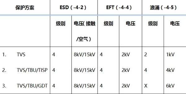
Figure 10: Comparison of protection levels of EMC solutions for three RS485 ports

Shijian Company also introduced two classic and practical RS-485 port protection solutions, which can pass IEC6100-4-2 ESD, IEC61000-4-4 EFT, IEC61000-4-5 Surge EMS safety test above level 4.
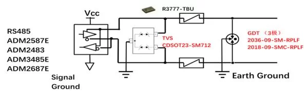

Solution 1: Adopt 3-pole GDT TBU TVS architecture solution
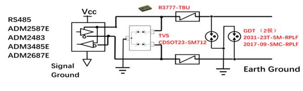
Solution 2: Adopt 2-pole GDT TBU TVS architecture solution

View more : IGBT modules | LCD displays | Electronic Components