Integrating the power module effectively and effortlessly into railway applications has been a great concern for an increasing number of power supply manufacturers. Such power modules should be adaptable to the system or environmental variations based on the specific applications. In this regard, an ultra-wide input range DC/DC converter can satisfy the requirements and support all nominal voltages for train-borne applications. Since the rail traffic is exposed to harsh environments, the DC/DC converter should be certified to the EN 50155, EN 61373, and EN 45545-2 standards.
One example that provides this adaptability is the EC7BW18-ECRT/EDRT DC/DC converter module from Cincon Electronics Co., Ltd. The series offers converters with all-in-one ultra-wide input voltages of 10 VDC to 160 VDC, available in chassis-mount or chassis-mount with DIN-rail options. The series meets EN 50155 standard with the fluctuation voltage range and supports distributed voltages of 24 VDC, 36 VDC, 48 VDC, 72 VDC, 96 VDC, and 110 VDC as shown in Table 1.

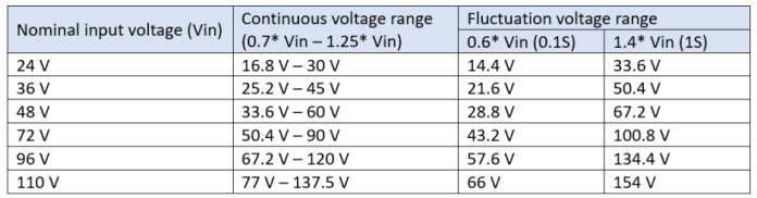
Table 1: EN 50155 input voltage range (Source: Cincon Electronics Co., Ltd.) Click for a larger image.
Why a turnkey solution

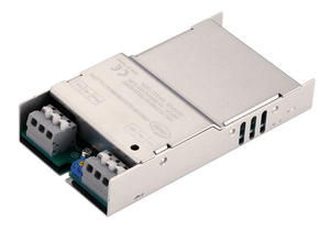
Cincon’s 20-W EC7BW18-ECRT/EDRT turnkey solution integrates the multi-functional power module for railway applications. (Source: Cincon Electronics Co.,Ltd.) Click for a larger image.
Some of the most complicated challenges in the modern railway sector that system designers face is how to handle electromagnetic interference (EMI), hold-up time, and inrush current issues. They must spend a lot of time on connecting the peripheral circuit to each circuit module for the control system.
A turnkey solution thus helps engineering designers be free from selecting external circuits, such as the inrush current limiter or noise filter for the power converter before mounting them. This turnkey solution includes built-in components, such as the inrush current limiter, noise filter, and hold-up circuit, to make it easier for system designers to integrate into the railway system. Using the turnkey converter solution, system designers simplify the task by only needing to install and test to see if it can work smoothly on the electronic apparatus. The solution also minimizes bill-of-material costs by reducing the number of external components. In addition, even if the turnkey converter fails, it can be just replaced in one module.

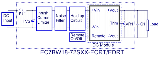
Figure 1: Block diagram of the EC7BW18-ECRT/EDRT (Source: Cincon Electronics Co., Ltd.)
Compliant with EN 50155
EN 50155 is a European standard for electronic systems in rolling stock for railway applications. Table 2 shows the tests such as temperature, humidity, vibration, shock, and other electrical aspects that the power converter must undergo before certification. The EC7BW18-ECRT/EDRT Series, as an example, has been examined in a harsh environment of a train-borne system and certified for the railway applications.

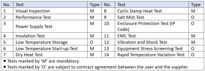
Table 2: EN 50155 tests (Source: Cincon Electronics Co., Ltd.) Click for a larger image.
Inrush current limiter
The DC/DC converter for railway applications requires a capacitor at the input side to maintain the hold-up time. Still, the transient characteristics of the capacitor will have higher inrush currents. Mitigating the inrush current is thus essential in case it causes a voltage drop in the front-end power supply or the over-current protection of the front-end power supply, resulting in no output from the converter.
To tackle these issues, the EC7BW18-ECRT/EDRT Series adopts a built-in active inrush limiter that offers higher efficiency. It is also less influenced by the ambient temperature. The graphs below indicate the different data of the inrush current with the same input voltage of 36 VDC via tests using two sets of the EC7BW18-72S05-ECRT. With the active inrush current limiter, the inrush current is 3.12 A in Figure 2, while Figure 3, without the inrush current limiter, is 27.6 A. If the input voltage becomes higher, the inrush current will be greater.

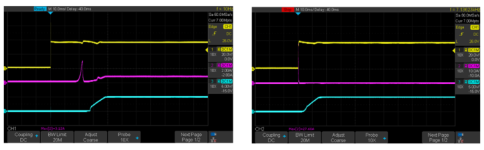
Figure 2 (left) with an inrush current limiter and Figure 3 (right) without an inrush current limiter. CH1 is the input voltage, CH2 is the input current, and CH3 is the output voltage. (Source: Cincon Electronics Co., Ltd.) Click for a larger image.
Hold-up circuit
Railway power systems are likely to have fluctuations of the supply voltage for a short period because they are impacted by the switch between the generator, battery, and pantograph. The situations can lead to a short-term open circuit or short circuit.
The EN 50155 power supply test, based on interruptions of voltage supply and supply change-over, is classified into different performance classes:
Interruptions of voltage supply:
- Class S1: No voltage interruption. No performance criterion is requested but the equipment shall continue to operate as specified after the voltage interruption.
- Class S2: Interruption time of 10 ms, performance criterion A
- Class S3: Interruption time of 20 ms, performance criterion A
Supply change-over:
- Class C1: At 0.6* Vin during 100 ms (without interruptions). Performance criterion A
- Class C2: During a supply break of 30 ms stating at Vin. Performance criterion B
In accordance with the requirements of S2, S3, and C2, it is essential to add a capacitor at the input side of the DC/DC converter. The capacitance value can be deduced by the formula as follows:
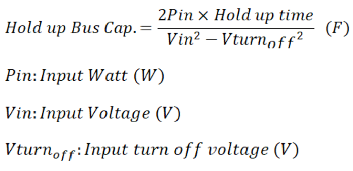

The formula reveals that with the same hold-up time and the lower voltage inputs, the greater the capacitance value required.
The EC7BW18-ECRT/EDRT provides a built-in hold-up circuit that meets the requirements of S2, S3, and C2. The graphs below show the hold-up time figures between two sets of the EC7BW18-72S05-ECRT, with and without a hold-up circuit. They both have the same input voltage of 24 VDC. However, the hold-up time for the test with a built-in hold-up circuit is 13 ms (Figure 4), compared with 0.88 ms without a hold-up circuit (Figure 5).

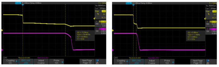
Figure 4 (left) with a hold-up circuit and Figure 5 (right) without a hold-up circuit. CH1 is the input voltage and CH2 is the output voltage. (Source: Cincon Electronics Co., Ltd.) Click for a larger image.
Highly integrated power modules include the EMI protection, inrush current limiter, and hold-up circuit. Approved by EN 50155, EN 50121-3-2, and EN 45545-2 standard, a turnkey solution offers several advantages for the railway industry. It provides an ultra-wide input voltage range of 10 VDC to 160 VDC, suitable for all kinds of voltage parameters across the different areas. In addition, the 16:1 input isolated DC/DC converter is applicable to the on-board rail apparatus, since the rail system voltage variability is larger.
The hold-up circuit, included in this example turnkey converter, acts as a buffer during an emergency despite a loss of input voltage. In addition, the EMI filter mitigates a sufficient level of emission and increases immunity against interference from susceptible electrical and electronic apparatus operated on the railway rolling stock. Meanwhile, the high efficiency up to 88% enables an operating temperature range of -40°C to 100°C. Thus a feature-rich turnkey converter solution can solve the thorny problem of power design and increase the stability of the railway system.