The servo motor is an older precise-positioning motor arrangement now facing some competition from the stepper motor.
Part 1 of this article introduced the concept of servo motors along with servo amplifiers and servo controllers. This part continues that exploration.
Q: What’s the history of servo motors?
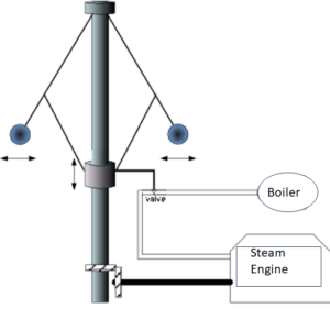
A: There were purely mechanical, closed-loop servo systems before electrical and electronic systems existed. For example, the centrifugal force/gravity-driven governor devised in conjunction with James Watts’ steam engine in the mid-1800s is a well-known example (Figure 1). This self-regulating governor was used to both set and maintain engine speed within a narrow range by increasing steam flow when the speed dropped and vice versa.

Electrical servo systems using magnetic elements were in use by the 1920s. One application of stepper motors using VR (Variable Reluctance) type motors was used by the British Navy for positioning control as well as remote control.
Q: Why is it even called a servo motor?
A: The origins are not clear, but it appears that the term “servo motor” in English comes from the French servomoteur used in the late 1800s. with the “servo” part is related to “serve” (or servir). J. L. Farcot used the term servomoteur in 1868 and used it in reference to a ship’s engine; in his book Le Servo-Moteur ou Moteur Asservi, published in 1873 he used asservi, meaning “subservient” or “enslaved,” as a synonym. English speakers translated it as “slave motor,”
Control signals and execution
Q: When did the electronic age of servos begin and how was it accomplished?
A: The first electronic systems were all analog, of course. The feedback signal was routed to an amplifier which compared it to the setpoint signal and amplified the difference. This difference voltage was then used to drive the servo motor. It took a lot of electronics and vacuum tubes, as well as space, weight, and power, to do this, but it worked.
Q: How has “modern” digital electronics affected the servo motor system design?
A: While the underlying closed-loop principle is unchanged, the signals and options have changed dramatically. First, while the feedback signal usually begins as an analog signal, it is soon digitized. It is then digitally compared to the setpoint value, and the error difference is used to drive the servo motor but does not do so directly. Instead, the difference signal is converted, in many designs, to a pulse-width modulated (PWM) signal which goes to a power amplifier which, in turn, controls the motor.
In other cases, PWM is not used. Instead, a variable-frequency signal is developed to control the AC motor. The type of control signal is a function of the motor type, but the loop is primarily digital.
Q: How do microcontrollers figure into the loop?
A: Microcontrollers support the use of sophisticated algorithms to be used to optimize the balance between performance factors such as acceleration, speed, smoothness, torque and holding power, minimal overshoot, and other properties. These algorithms usually begin with the PID strategy which is then tuned to the specifics of the application and motor; it may also have some added features to meet the unique requirements of the precision-positing scenario.
Q: Why use a servo motor rather than a stepper motor?
A: Each has a mix of attributes, and the right choice depends on the application. Keep in mind that a stepper is generally used in an open-loop system, while a servo is a closed-loop system (Figure 2).


The top-level perspective on the relative attributes of each approach is illustrative (Figure 3).


Q: Is there another way to look at servo motors versus steppers?
A: You can look at their pros and cons in Figure 4. It is important to note that there are many exceptions to these general guidelines.


There are differences in speed and torque (both static and dynamic), accuracy and resolution, speed of response, and control and feedback mechanisms. In terms of best-fit applications, servo motors are generally better suited for robotics, machine tools, manufacturing lines, and mil/aerospace. Steppers are better for printers (both paper and 3D), linear actuators, medical devices, and PZT (pan, zoom, tilt) camera positions, but, again, there are many exceptions.
Servo controller hardware
Q: What circuitry is needed to build a servo controller?
A: The answer depends on the accuracy needed, and the motor type and size. A basic but serviceable, limited-function PWM servo motor controller for very small motors can be built with the classic, ubiquitous 555 timer IC, but a separate microcontroller (Figure 5) must provide the overall direction.


A much more sophisticated approach is offered by the Trinamic TMC4671 (Trinamic was purchased by Maxim Integrated, which in turn has become part of Analog Devices) (Figure 6). This IC is a fully integrated servo controller, providing field-oriented control (FOC) for BLDC/PMSM and 2-phase stepper motors, as well as DC motors and voice coils.


It provides torque control, field-oriented control (FOC), velocity control, and position control and integrates an analog/digital converter, as well as an encoder interface and a fast PWM engine operating from 25 kHz to 100 kHz.


Q: What does a commercial servo controller unit look like?
A: In a typical modern system, the servo controller is a smart, processor-based controller circuit providing many of the needed functions along with analog and digital I/O as needed. For smaller systems, the power-amplifier devices for the motor may be co-located on the same circuit board or a small, adjacent board.
For larger systems with higher-power motors, the controller and amplifier are housed in an independent chassis, often mounted to a standard enclosure such as the DIN rail (Figure 7). Many such units feature multiple system and motor I/O connections as well as connectivity, including Ethernet and various industrial busses.
Conclusion
Servo motors and their drive amplifiers play an important role in modern precision-positioning systems ranging from small desktop units to large industrial systems. They provide superior performance under challenging circumstances and offer the confidence that a closed-loop feedback architecture provides. However, due to their complexity, users must use care in the system and motor selection to meet the multiple design objectives. Modern servo motors and controllers greatly ease and simplify the entire process while offering the capabilities of closed-loop systems.
EE World related content
What is Proportional (PID) Control and why is it used? (Part 1)
Basics of motion-control profiles, Part 1: Context
Basics of motion-control profiles, Part 2: Ramp profiles
Basics of motion-control profiles, Part 3: Implementations
Motor field-oriented control, Part 1: Principles
Motor field-oriented control, Part 2: Implementation
Motor fundamentals and DC motors
Driving brushed and brushless DC motors
The basics of AC motors and their applications
Difference between synchronous and asynchronous (induction) motors
How many electric motors are in a car?
What you need to know about MCUs for servo control
External References
RealPars B.V., “What is a Servo Motor and How it Works?”
ISL Products International Ltd., “Servo Motor Fundamentals”
Kollmorgan, “What is a Closed-Loop System?”
Association for Advancing Automation, “Servo Motors vs. Stepper Motors in Motion Control: How to Choose the Right One for Your Application”
Wevolver, “Stepper vs Servo Motors: A Comprehensive Comparison for Your Next Project”
Control Automation, “Servo Motor vs Stepper Motor: Understanding the Differences”
Machine Design, “Stepper and Servo Motor Tradeoffs”
ElProCus, “Different Types of Servo Motors: DC Servo Motor and AC Servo Motor”
Advanced Motion Controls, “Is it Servo Drive or Servo Amplifier? and Other Motion Control Questions”
Advanced Motion Controls, “Why Choose a Servo Drive vs a VFD?”
Advanced Motion Controls, “Stepper vs Servo”
ACS Industrial Services, Inc., “How to tell the Difference Between A Servo Controller and A Servo Drive or Amplifier”
Robots.com, “A Little about Servo Amplifiers”
Engineer’s garage/EE World Online, “Servo Motor Control Using 555 Timer IC”
Trinamic/Analog Devices. “TMC4671 Datasheet”
John Hannavy, “The Governor – controlling the power of steam machines”
Radwell International, “The Evolution of the Servo Motor”
IEEE Industry Applications Magazine (Volume: 2, Issue: 2, March-April 1996), “Origins of the Servo-Motor”
Rexroth Products, “Why Do We Call It a Servomotor?”
Semantic Scholar/IEEE, “Origins of the Servo-Motor”