FF300R12KE3_B2: A Technical Analysis for High-Power Applications
## FF300R12KE3_B2: Infineon 1200V 300A EconoDUAL™ 3 IGBT Module
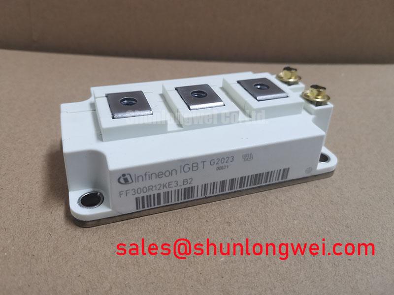
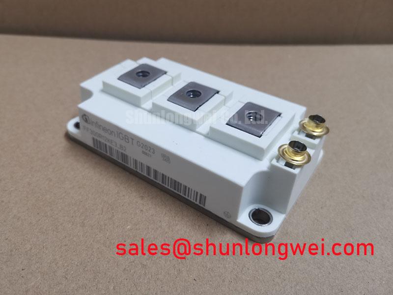
The Infineon FF300R12KE3_B2 is a 1200V, 300A half-bridge IGBT module housed in the industry-recognized EconoDUAL™ 3 package. This module integrates TRENCHSTOP™ IGBT3 and Emitter Controlled diode technology, establishing a benchmark for low conduction and switching losses. It provides engineers with a robust and efficient solution for high-power conversion systems. The module’s design focuses on delivering a balance between performance and long-term operational reliability.
* **Core Specifications**: 1200V | 300A | VCE(sat) (typ.) 1.70V
* **Key Advantages**: Low VCE(sat) reduces conduction losses and thermal load. A high maximum operating junction temperature (Tvj op) of 150°C provides a significant thermal overhead.
* **Design Utility**: The low thermal resistance and integrated NTC thermistor facilitate precise thermal management and system protection.
Download Official Datasheet (PDF)

Technical Analysis for System Integration
The engineering value of the FF300R12KE3_B2 is rooted in its balanced electrical and thermal characteristics. The core of this module is the TRENCHSTOP™ IGBT3, which represents a significant step in reducing the collector-emitter saturation voltage (VCE(sat)). With a typical VCE(sat) of just 1.70V at its nominal current of 300A (at 25°C), this module minimizes power dissipated as heat during the on-state. Think of VCE(sat) as a toll for current flow; a lower toll means less energy is wasted, directly contributing to higher inverter efficiency and potentially smaller heatsink requirements.
Thermal stability is a cornerstone of this module’s design. It is rated for a maximum operating junction temperature of 150°C and a short-term overload temperature of 175°C. This wide operating window provides a substantial safety margin in demanding applications. The module’s thermal resistance from junction to case (RthJC) is specified at a low 0.058 K/W for each IGBT. This low resistance value is critical, acting like a wide pipe that allows heat to be efficiently transferred from the semiconductor die to the heatsink. This facilitates a more compact and cost-effective cooling system design while ensuring long-term power cycling capability.
The inclusion of a pre-applied Thermal Interface Material (TIM) in select sub-models of this series further simplifies manufacturing and enhances thermal performance. This factory-applied layer ensures a uniform and reliable thermal connection between the module and the heatsink, removing process variables from the assembly line. The module also features a standard 10µs short-circuit withstand time, providing essential robustness against fault conditions in the system.
Optimized Application Scenarios
The FF300R12KE3_B2 is engineered for a range of high-power applications where efficiency and reliability are paramount.
* **Variable Frequency Drives (VFDs):** Its half-bridge configuration is the fundamental building block for three-phase inverters. The low VCE(sat) and robust thermal performance are ideal for controlling motor speed and torque efficiently.
* **Solar Inverters:** The module’s 1200V blocking voltage and high efficiency are well-suited for converting DC power from photovoltaic arrays to grid-compliant AC power.
* **Uninterruptible Power Supplies (UPS):** In UPS systems, this module ensures reliable and efficient power conversion to protect critical loads during power outages.
* **Welding Equipment:** Capable of handling the high-current, pulsed-load conditions characteristic of modern welding power supplies.
This module’s specifications make it an optimal choice for industrial motor drives and power converters requiring a proven, efficient, and thermally stable switching solution.
Key Specifications of the FF300R12KE3_B2
| Parameter | Symbol | Condition | Value | Unit |
|---|---|---|---|---|
| Absolute Maximum Ratings | ||||
| Collector-Emitter Voltage | VCES | Tvj = 25°C | 1200 | V |
| Continuous DC Collector Current | IC nom | TC = 80°C, Tvj max = 150°C | 300 | A |
| Repetitive Peak Collector Current | ICRM | tp = 1 ms | 600 | A |
| Gate-Emitter Voltage | VGES | ±20 | V | |
| IGBT, Inverter – Electrical Characteristics | ||||
| Collector-Emitter Saturation Voltage | VCE sat | IC = 300 A, VGE = 15 V, Tvj = 25°C | 1.70 (typ) / 2.00 (max) | V |
| Gate Threshold Voltage | VGE(th) | IC = 12.0 mA, VCE = VGE, Tvj = 25°C | 5.0 to 6.5 | V |
| Module Characteristics | ||||
| Isolation Test Voltage | VISOL | RMS, f = 50 Hz, t = 1 min. | 2.5 | kV |
| Thermal Resistance, Junction-to-Case | RthJC | per IGBT | 0.058 | K/W |
Note: All specifications are based on the official datasheet at Tvj = 25°C unless otherwise noted. Refer to the datasheet for complete characteristic curves and test conditions.
Engineer’s FAQ
- What is the recommended gate driver voltage for the FF300R12KE3_B2?
- The datasheet specifies a recommended turn-on gate-emitter voltage (VGEon) of +15V and a turn-off voltage (VGEoff) of -15V. Using these values ensures the device operates at its specified VCE(sat) and switching characteristics.
- How do I ensure reliable thermal design for this 300A module?
- Effective thermal design requires calculating the total power loss (Ptot = Pcond + Psw) using the graphs in the datasheet. Then, select a heatsink where its thermal resistance (RthHA) meets the condition: RthHA ≤ (Tvj max – TA) / Ptot – RthJC – RthCH. For the FF300R12KE3_B2, the IGBT’s RthJC is 0.058 K/W. A precise RthCH (case-to-heatsink) value depends on your mounting method and thermal interface material. The integrated NTC provides real-time temperature feedback for active thermal management.
- Can multiple FF300R12KE3_B2 modules be paralleled for higher current?
- Yes, paralleling is feasible. The TRENCHSTOP™ IGBT3 technology features a positive temperature coefficient for VCE(sat), which aids in balancing current sharing between modules. For successful paralleling, it is critical to ensure a symmetrical, low-inductance busbar layout and use individual gate resistors for each module to prevent oscillations. Refer to Infineon’s application notes on IGBT paralleling for detailed layout guidance.
- What is the function of the Emitter Controlled diode in this module?
- The Emitter Controlled diode is a freewheeling diode (FWD) co-packed with the IGBT. It is optimized for soft recovery characteristics. This softness reduces voltage overshoots and electromagnetic interference (EMI) during the diode’s turn-off, which is crucial for reliable operation in inverter circuits where the diode commutates current from an inductive load.
Enabling Efficient and Robust Power Conversion
The Infineon FF300R12KE3_B2 module provides a verified, high-performance foundation for power electronics engineers. By combining the efficiency of TRENCHSTOP™ IGBT3 technology with the reliable EconoDUAL™ 3 housing, this module enables the development of power converters that are not only efficient but also robust and manufacturable at scale. Its documented thermal performance and electrical characteristics allow for precise, data-driven system design.