Fuji 1MBI200HH-120L-50 IGBT Module: A Technical Review for High-Frequency Designs
Fuji 1MBI200HH-120L-50 IGBT Module | 1200V 200A
Introduction and Core Highlights
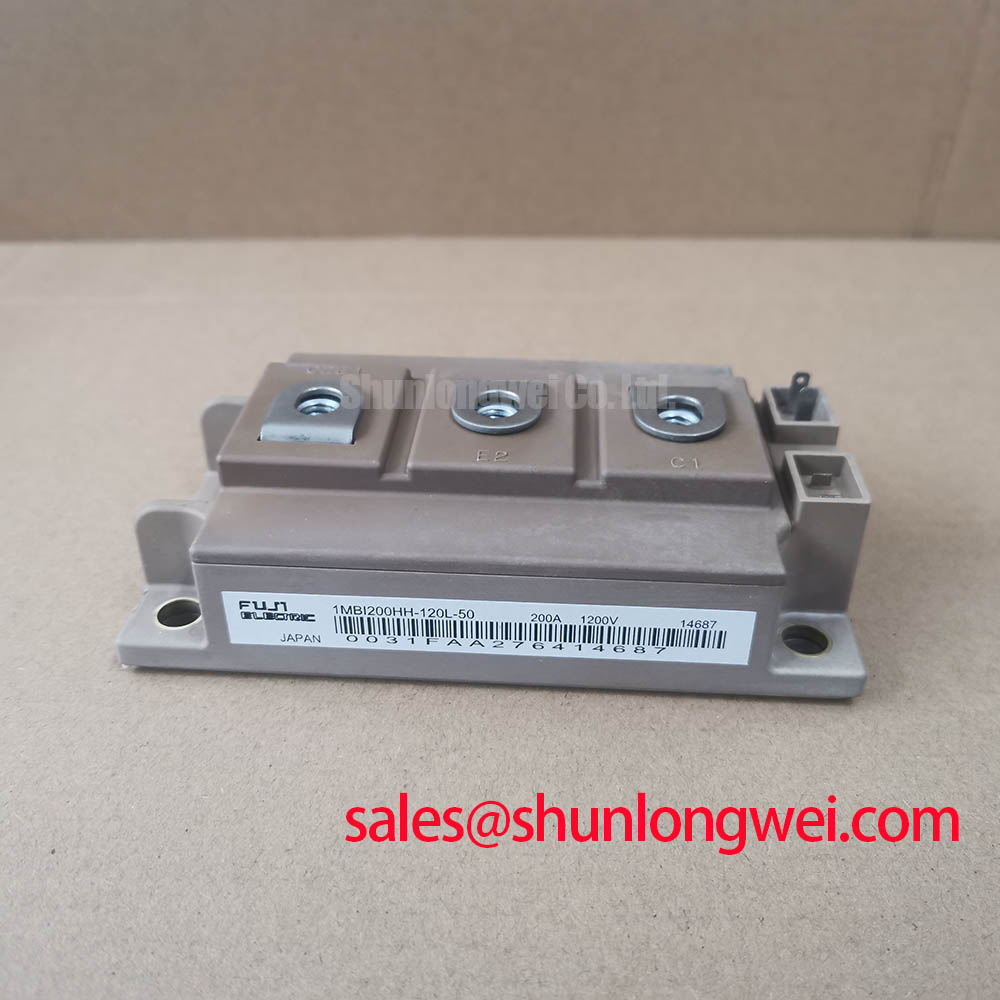
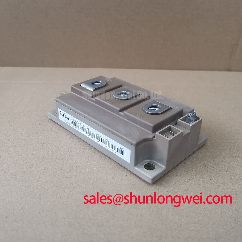
This Fuji Electric 1MBI200HH-120L-50 is a single IGBT module engineered for high-frequency power conversion, delivering a distinct combination of rapid switching and minimized energy loss. By leveraging Fuji’s V-Series chip technology, this component enables designers to achieve higher operational efficiencies. It addresses the critical need for reducing switching losses in high-frequency topologies, which directly translates to lower operating temperatures and improved system reliability. The module’s thermal characteristics also facilitate more predictable and manageable thermal design.
- Core Specifications: 1200V | 200A (Tc=80°C) | Eoff 28.0 mJ (typ)
- Key Advantages: Reduced energy dissipation in high-frequency circuits, simplified thermal management through low junction-to-case thermal resistance.
Download Official Datasheet (PDF)

Technical Analysis of High-Speed Performance
The defining characteristic of the 1MBI200HH-120L-50 is its optimization for high-speed operation, a factor directly substantiated by its switching energy values. The datasheet specifies a typical turn-on switching loss (Eon) of 34.0 mJ and a turn-off switching loss (Eoff) of 28.0 mJ under rated conditions (Tj=150°C). In applications such as solar inverters or welding power supplies operating at several kilohertz, these seemingly small energy figures per cycle accumulate into significant power dissipation. The module’s low Eoff value is particularly beneficial as it reduces the primary source of switching loss in many hard-switched converter designs, leading to greater overall system efficiency.
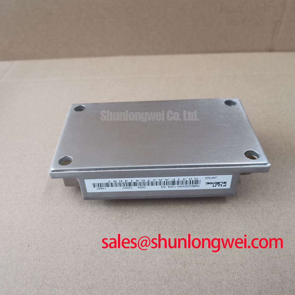
Effective thermal management is fundamental to leveraging the module’s performance without compromising its lifespan. The datasheet specifies a thermal resistance from junction to case (Rth(j-c)) for the IGBT at 0.09 K/W. This parameter can be imagined as the width of a pipe for heat flow; a lower value signifies a wider pipe, allowing heat to escape the semiconductor junction more easily. This low thermal impedance ensures that the heat generated during operation can be efficiently transferred to an external heatsink, maintaining the junction temperature within safe operating limits and contributing to the module’s long-term reliability. A proper understanding of this value is crucial for preventing premature failures.
Optimized Application Scenarios
The electrical and thermal characteristics of this module align it with specific high-performance applications:
- High-Frequency Solar Inverters: The low switching losses are critical for maximizing energy conversion efficiency at the elevated frequencies used in modern photovoltaic systems.
- Uninterruptible Power Supplies (UPS): Fast switching allows for smaller magnetic components and higher power density, especially in double-conversion online UPS topologies.
- Industrial Motor Drives: Enables precise and efficient control in high-performance servo and Variable Frequency Drives (VFDs) where fast current response and low losses are necessary.
- Welding Power Supplies: The module’s robust performance and high-speed operation are well-suited for the demanding, high-frequency switching cycles in inverter-based welders.
Its specifications are an excellent match for high-frequency power conversion systems where efficiency and thermal stability are primary design criteria.
Key Specification Parameters
| Absolute Maximum Ratings (at Tc=25°C unless otherwise specified) | |
|---|---|
| Collector-Emitter Voltage (Vces) | 1200 V |
| Gate-Emitter Voltage (Vges) | ±20 V |
| Continuous Collector Current (Ic) @ Tc=80°C | 200 A |
| Max. Power Dissipation (Pc) | 1380 W |
| Operating Junction Temperature (Tj) | +150 °C |
| Electrical Characteristics (at Tj=25°C unless otherwise specified) | |
| Collector-Emitter Saturation Voltage (Vce(sat)) (Ic=200A, Vge=15V, Tj=125°C) | 2.3 V (Typ) / 2.7 V (Max) |
| FWD Forward Voltage (Vf) (Ie=200A, Vge=0V, Tj=125°C) | 2.0 V (Typ) / 2.4 V (Max) |
| Turn-off Switching Loss (Eoff) (Tj=150°C) | 28.0 mJ (Typ) |
| Short-Circuit Withstand Time (tsc) (Vcc=600V, Vge≤15V, Tj=150°C) | 10 µs |
| Thermal Resistance, Junction to Case (Rth(j-c)) – IGBT | 0.09 K/W (Max) |
Engineer’s FAQ
1. What are the key factors for minimizing switching losses with the 1MBI200HH-120L-50?
To minimize switching losses, focus on the gate drive circuit. The selection of the external gate resistor (Rg) is critical; a smaller Rg speeds up switching but may increase voltage overshoot and EMI. The datasheet provides switching loss data with a specific Rg value as a reference. Additionally, minimizing parasitic inductance in the PCB layout is vital for managing fast switching transients.
2. How does the case temperature (Tc) affect the module’s maximum continuous collector current (Ic)?
The maximum allowable collector current is inversely related to the case temperature. The datasheet’s “Collector current vs. Case temperature” graph shows that the rated 200A is achievable at Tc=80°C. Above this temperature, the current must be derated to keep the junction temperature below the 150°C maximum. This underscores the necessity of an efficient heatsinking solution.
3. Is a negative gate voltage required for turn-off?
The datasheet electrical characteristics are specified with a turn-off gate voltage of 0V. While not strictly required, applying a negative gate voltage (e.g., -5V to -15V) during the off-state is a common and recommended practice. It provides a larger margin against noise and dV/dt induced turn-on, enhancing the reliability of the system, particularly in noisy, high-frequency environments. For more on this topic, consider reading about robust gate drive design.
Design Considerations
The 1MBI200HH-120L-50 IGBT module offers a validated component choice for power systems requiring high-speed operation. Its documented low switching losses and efficient thermal transfer provide the technical foundation for developing compact, reliable, and highly efficient power converters. Proper implementation of gate drive and thermal solutions will enable designers to fully realize the performance benefits defined in its datasheet.