Fuji 1MBI600LN-060: A Technical Guide to a 600A High-Current IGBT Module
Fuji 1MBI600LN-060 IGBT Module | 600V 600A
Technical Introduction to a High-Current Power Switching Solution
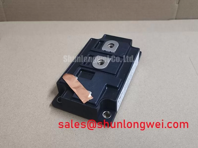
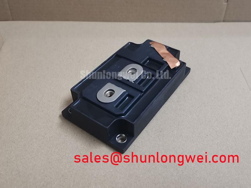
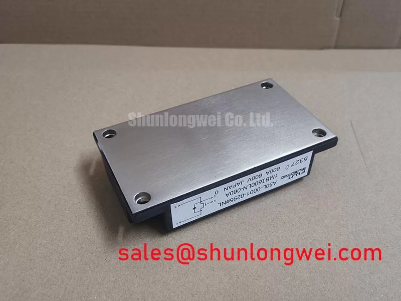
The Fuji Electric 1MBI600LN-060 is a single IGBT module engineered for high-current power conversion systems. This device provides robust control over substantial electrical loads by combining a high current rating with a low on-state voltage, a key value proposition for improving system efficiency. It is built using Fuji’s N-Series Non-Punch-Through (NPT) technology, which offers a balance of performance and ruggedness for industrial applications.
- Core Specifications: 600V | 600A (DC) | VCE(sat) 1.9V (typ)
- Key Advantages: Minimizes conduction losses, simplifies thermal design
This module’s specifications are well-suited for engineers designing systems where high current capability is a primary requirement. For detailed electrical and thermal performance graphs, please download the official datasheet (PDF).


Technical Analysis for System Design
The engineering value of the 1MBI600LN-060 is rooted in its high-current handling and thermal characteristics. With a continuous collector current (IC) rating of 600A at a case temperature of 80°C and a peak current capability of 1200A, this module is specified for substantial power loads. This high capacity allows designers to avoid complex paralleling of smaller IGBTs, which simplifies gate drive circuitry and mitigates challenges related to ensuring equal current sharing among devices.
A critical parameter for efficiency is the collector-emitter saturation voltage (VCE(sat)), which is typically 1.9V at the nominal 600A current. This low on-state voltage directly translates to reduced conduction losses, a primary source of heat in high-current applications. The module’s thermal resistance from junction to case (Rth(j-c)) is specified at a maximum of 0.05 °C/W for the IGBT. Think of thermal resistance as the narrowness of a pipe; a lower value represents a wider pipe that allows heat to flow away from the silicon chip more easily. This efficient heat transfer is crucial for maintaining reliability under sustained loads, a topic further explored in guides on IGBT thermal design.
Optimized Application Scenarios
The specific characteristics of the 1MBI600LN-060 make it well-suited for several industrial applications:
- High-Power Motor Drives: Its 600A continuous current rating allows for precise and robust control of large industrial AC motors and DC choppers where torque and reliability are critical.
- Welding Power Supplies: The 1200A peak current rating (Icp) provides the necessary overhead to handle the demanding, pulsed-load nature of industrial welding equipment.
- Uninterruptible Power Supplies (UPS): The combination of high current handling and low conduction loss makes it an efficient choice for the inverter stage in large-scale UPS systems.
- High-Current Converters: Suitable for various DC-DC and DC-AC converters where managing high power throughput is the primary objective.
This module is best matched for low-to-medium frequency applications where minimizing on-state power loss and ensuring robust performance under high current are the main design priorities.
Key Specification Parameters
| Absolute Maximum Ratings (Tc=25°C unless otherwise noted) | ||
|---|---|---|
| Collector-Emitter Voltage (VCES) | – | 600V |
| Gate-Emitter Voltage (VGES) | – | ±20V |
| Continuous Collector Current (IC) | Tc=80°C | 600A |
| Pulsed Collector Current (Icp) | 1ms | 1200A |
| Max Power Dissipation (PC) | – | 2500W |
| Operating Junction Temperature (Tj) | – | -40 to +150°C |
| Isolation Voltage (Visol) | AC, 1 minute | 2500V |
| Electrical Characteristics (Tj=25°C) | ||
| Collector-Emitter Saturation Voltage (VCE(sat)) | IC=600A, VGE=15V | 1.9V (Typ), 2.5V (Max) |
| Gate-Emitter Threshold Voltage (VGE(th)) | IC=600mA, VCE=20V | 3.0V (Min), 6.0V (Max) |
| Input Capacitance (Cies) | VCE=25V, VGE=0V, f=1MHz | 65nF (Typ) |
Engineer FAQ
What are the key thermal considerations when designing with the 1MBI600LN-060?
The main consideration is effectively managing the power dissipated as heat. With a maximum power dissipation of 2500W, a low-resistance thermal path is essential. This requires selecting an appropriate heatsink based on the module’s thermal resistance (Rth(j-c) max of 0.05°C/W) and applying a quality thermal interface material. Proper mounting torque on the M6 screws is also vital to ensure optimal contact between the module’s baseplate and the heatsink.
What is the recommended gate voltage (VGE) for this module?
The datasheet specifies the turn-on gate voltage condition for VCE(sat) as +15V. The absolute maximum gate-emitter voltage is ±20V. Operating at the recommended +15V ensures the IGBT is fully saturated (turned on) for the lowest conduction loss. A negative gate voltage (e.g., -5V to -15V) is recommended for turn-off to provide better noise immunity and prevent parasitic turn-on, a crucial aspect of robust gate drive design.
Does this module include a freewheeling diode (FWD)?
No, the 1MBI600LN-060 is a single IGBT module without an integrated freewheeling diode. For applications with inductive loads, such as motor drives or inverters, an external fast-recovery diode must be connected anti-parallel to the IGBT. The datasheet explicitly recommends using a companion FWD, such as Fuji’s ERD60-100, for this purpose.
Enabling High-Power System Design
The 1MBI600LN-060 provides a direct path for engineers to manage high-current loads efficiently. Its low on-state voltage minimizes thermal overhead, while its robust NPT construction ensures reliable operation in demanding industrial environments. This focus allows for the development of power-dense converters and drives that are both effective and dependable.