Fuji Electric 2MBI100N-060: A Technical Guide to the 600V 100A Dual IGBT Module
Fuji Electric 2MBI100N-060 IGBT Module: 600V 100A Dual Switch
M2: High-Efficiency Switching with the Fuji 2MBI100N-060
The 2MBI100N-060 is a dual-channel Insulated Gate Bipolar Transistor (IGBT) module from Fuji Electric, recognized for its balance of high-speed switching and robust current handling. This module is specifically engineered to optimize conduction and switching losses in medium-voltage power conversion systems. By integrating two IGBT switches in a single housing, it provides a compact solution for half-bridge circuit topologies commonly found in industrial motor drives and power supplies.
- Core Specifications: 600V Collector-Emitter Voltage | 100A Continuous Collector Current | VCE(sat) Typical 2.1V.
- Key Advantages: Minimized thermal dissipation requirements through optimized saturation voltage; enhanced reliability in high-frequency PWM applications due to soft-recovery free-wheeling diodes.
A frequent question for engineers is how to calculate heatsink requirements for high-current modules. The 2MBI100N-060 addresses this by providing low junction-to-case thermal resistance, allowing for more compact cooling architectures.
Download Official 2MBI100N-060 Datasheet (PDF)
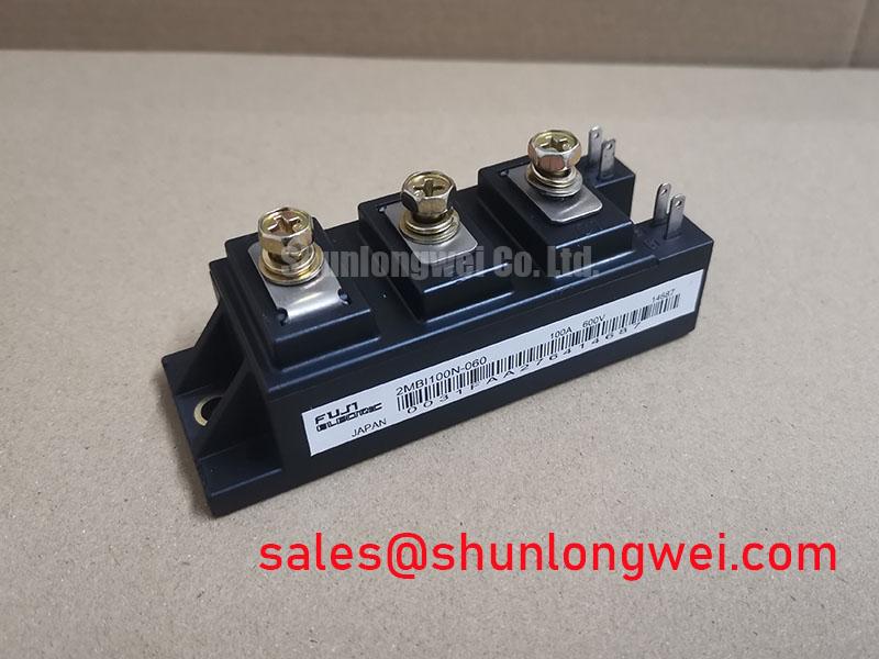
M3: Engineering Analysis of Conduction and Thermal Resistance
The 2MBI100N-060 leverages a standard N-series architecture to maintain a stable Collector-Emitter Saturation Voltage (VCE(sat)). In power electronics, VCE(sat) is a critical determinant of conduction loss. You can think of this voltage drop as a “narrow door” in a hallway; the wider the door (lower the voltage drop), the easier the 100A current can flow through without generating excessive heat through friction. At a typical 2.1V drop, this module ensures that power loss is kept within manageable limits during continuous operation.
Thermal management is further supported by the module’s low thermal resistance (Rth). If we imagine thermal resistance as the thickness of a wall separating a hot room from a cold one, the 2MBI100N-060 provides a “thin, conductive wall” that allows heat to escape the silicon junction and reach the baseplate efficiently. This characteristic is vital for preventing thermal runaway and mitigating risks associated with IGBT latch-up during high-stress transients.

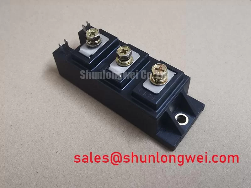
Beyond conduction, the switching performance is tuned for soft recovery. High-speed switching often introduces electromagnetic interference (EMI) and voltage spikes. The integrated diodes in the 2MBI100N-060 are characterized by soft-switching properties, which reduce the dV/dt stress on the surrounding circuitry. This design choice simplifies the gate drive requirements and reduces the reliance on large snubber circuits.
M4: Optimized Application Scenarios
- General Purpose Inverters: The 600V rating is ideal for standard 220V/240V AC motor control, where the 2MBI100N-060 provides a reliable buffer against line voltage fluctuations.
- Uninterruptible Power Supplies (UPS): High switching frequency capabilities allow for smaller filter components in the output stage, increasing overall system power density.
- DC-DC Converters: Soft recovery diodes minimize losses during high-frequency energy transfer, making it suitable for industrial battery charging systems.
- AC Servo Drives: The precise switching control supports the high-dynamic response required in robotic motion control.
Best Match: Ideal for industrial VFDs requiring a balanced 600V/100A switch with low conduction losses and minimal EMI footprints in compact designs.
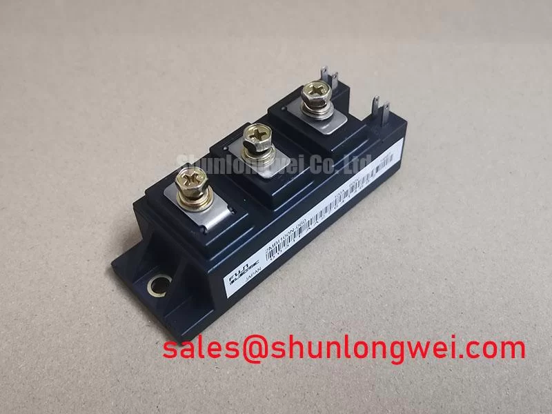

M5: Key Technical Specifications
| Absolute Maximum Ratings (at Tc=25°C) | |
|---|---|
| Collector-Emitter Voltage (Vces) | 600V |
| Gate-Emitter Voltage (Vges) | ±20V |
| Continuous Collector Current (Ic) | 100A |
| Pulsed Collector Current (Icp) | 200A |
| Electrical Characteristics (Typical) | |
| VCE(sat) @ Ic=100A, Vge=15V | 2.1V (2.8V Max) |
| Gate Threshold Voltage (Vge(th)) | 4.5V to 7.5V |
| Input Capacitance (Cies) | 10,000pF |
| Thermal Characteristics | |
| Thermal Resistance (j-c) per IGBT | 0.31 °C/W |
| Thermal Resistance (j-c) per Diode | 0.70 °C/W |

M6: Engineer’s Frequently Asked Questions
Q1: What is the recommended mounting torque for the 2MBI100N-060 to ensure proper thermal contact?
A: Based on standard Fuji Electric IGBT module guidelines, the mounting screws (M5) should typically be tightened to 2.5 to 3.5 N·m. Insufficient torque leads to poor thermal transfer, while over-tightening can crack the ceramic substrate or warp the baseplate.
Q2: How does temperature affect the saturation voltage of this module?
A: The 2MBI100N-060 exhibits a positive temperature coefficient for VCE(sat). As the junction temperature increases, the saturation voltage also rises. This is beneficial for load sharing when modules are operated in parallel, as it helps prevent thermal runaway in a single device.
Q3: Can this module be used in 480V AC applications?
A: Generally, no. A 600V Vces rating does not provide sufficient safety margin for 480V systems, which typically see peak voltages and surges exceeding 700V. This model is best suited for power semiconductors applications in 200V to 240V AC networks.
M7: Final Design Considerations
The Fuji Electric 2MBI100N-060 stands as a reliable workhorse for mid-range power switching requirements. Its dual-switch configuration and optimized thermal architecture provide a predictable platform for engineers developing high-performance inverters and UPS systems. By prioritizing low conduction loss and stable switching characteristics, it ensures long-term operational stability in demanding industrial environments.