Fuji Electric 6MBI450U-120-02 1200V 450A IGBT Module: Technical Analysis and Design Guide
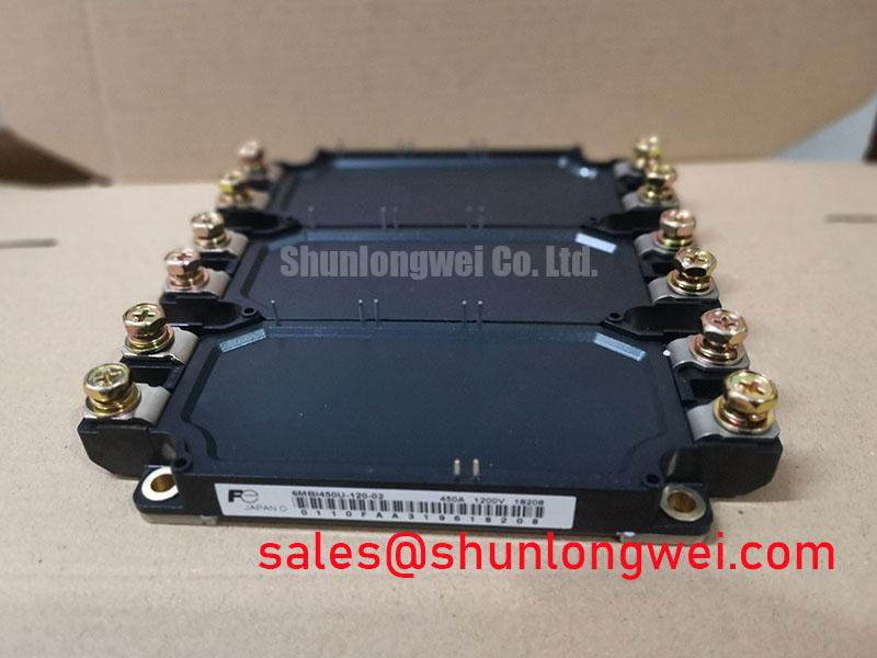
6MBI450U-120-02 Fuji Electric 1200V 450A IGBT Module
Introduction and Core Highlights
The 6MBI450U-120-02 is a high-power six-pack IGBT module manufactured by Fuji Electric, configured for three-phase inverter topologies. Integrating six IGBT switches into a single package, this module delivers optimized thermal performance and reduced parasitic inductance. It serves as a space-saving building block for industrial power conversion systems.
- Core Ratings: 1200V | 450A | VCE(sat) 1.90V (typical)
- Engineering Benefits: Lower conduction losses, simplified busbar layout, and stable operation under thermal stress.
For detailed electrical curves and mechanical dimensions, you can download the official Fuji Electric 6MBI450U-120-02 datasheet (PDF).
Technical Analysis of Conduction and Thermal Performance
The Fuji Electric 6MBI450U-120-02 utilizes trench-gate technology to achieve a low typical collector-emitter saturation voltage (VCE(sat)) of 1.90V. Lower saturation voltage directly translates to reduced conduction losses during high-current operations. Designers seeking details on this series can refer to the Fuji 6MBI450U-120 IGBT technical breakdown.
You can visualize the collector-emitter saturation voltage as a narrow bottleneck in a water pipe. A lower voltage drop means less energy is restricted and converted to waste heat, allowing the system to run cooler and more efficiently under high current loads. This reduction in waste heat simplifies the selection of heatsinks and cooling systems.
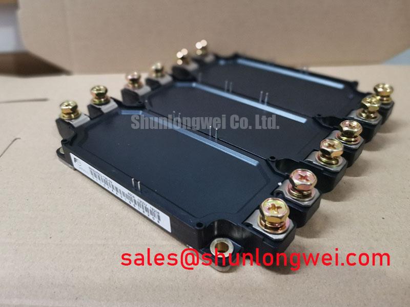
Thermal management is supported by an alumina isolation substrate bonded to a copper baseplate. The junction-to-case thermal resistance (Rth(j-c)) is limited to 0.065°C/W for the IGBT portion. This efficient heat transfer path protects the silicon chips from thermal runaway during continuous load transients. Additional security is provided in systems featuring an integrated NTC thermistor for real-time temperature tracking.
To combat electromagnetic interference (EMI) and transient overvoltage during fast turn-off, the module is structured to minimize internal package inductance. High stray inductance can lead to severe voltage spikes that stress the collector-emitter junction. Controlling parasitic inductance helps prevent latch-up and prolongs the system lifetime under rapid switching frequencies.

Optimized Application Scenes
- Industrial Motor Drives (VFDs): The six-pack layout provides a complete three-phase inverter stage in a unified package. This reduces installation volume while ensuring symmetric path lengths for balanced phase currents.
- Uninterruptible Power Supplies (UPS): Fast switching capability combined with a high 1200V rating supports efficient double-conversion topologies and safe energy storage interfaces.
- Solar Inverters: The 450A current handling capacity allows for high power throughput, translating solar DC power to grid-compliant AC lines with minimal thermal accumulation.
This module is optimized for high-power three-phase conversion systems requiring low conduction losses and compact layouts in power semiconductors applications.
Key Specifications Table
| Parameter | Symbol | Typical / Value | Unit |
|---|---|---|---|
| Absolute Maximum Ratings (per switch) | |||
| Collector-Emitter Voltage | VCES | 1200 | V |
| Gate-Emitter Voltage | VGES | ±20 | V |
| Continuous Collector Current (TC = 80°C) | IC | 450 | A |
| Pulsed Collector Current (1ms) | ICP | 900 | A |
| Electrical Characteristics (Tj = 25°C) | |||
| Collector-Emitter Saturation Voltage (IC = 450A, VGE = 15V) | VCE(sat) | 1.90 | V |
| Gate-Emitter Threshold Voltage (VCE = 20V, IC = 450mA) | VGE(th) | 4.5 to 8.5 | V |
| Thermal Resistance Characteristics | |||
| IGBT Junction-to-Case Thermal Resistance | Rth(j-c) | 0.065 (max) | °C/W |

Engineer FAQ
Q1: How do you calculate the thermal dissipation for the 6MBI450U-120-02?
A1: Calculate total power loss (conduction plus switching losses) for each IGBT and diode switch. Multiply this loss by the junction-to-case thermal resistance (Rth(j-c) = 0.065°C/W) to determine the thermal delta between the silicon junction and the module case.
Q2: Why is the six-pack integrated package layout selected over discrete switches?
A2: The six-pack configuration houses the entire three-phase bridge in a single housing. This reduces connection routing lengths, controls stray parasitic inductance, and guarantees better thermal uniformity across all six switches during high-power inverter operations.
Q3: Does the 6MBI450U-120-02 require isolated gate drive power supplies?
A3: Yes. High-side switches do not share a common emitter potential. Therefore, they require three independent, isolated gate drive power supplies, while the low-side switches typically share a common ground reference depending on driver design.
Design Integration Summary
Offering 450A switching capability at 1200V within a compact six-pack package, this module allows power electronics engineers to construct compact industrial inverters. The low collector-emitter saturation voltage and low package inductance ensure a stable and cool-running conversion stage under variable load profiles.