Hitachi MBM300HR6HY 1700V 300A IGBT Module: Technical Analysis and Applications
Hitachi MBM300HR6HY 1700V 300A IGBT Module
Introduction and Core Highlights
The Hitachi MBM300HR6HY is a high-power, high-voltage silicon device within our catalog of power semiconductors. It is designed for demanding power conversion systems. This module features a 1700V blocking voltage and a 300A continuous collector current, offering excellent performance under harsh electrical conditions. The module integrates an insulated baseplate to optimize heat dissipation and prevent premature dielectric breakdown.
- Core Specifications: 1700V | 300A | Single IGBT Module
- Key Benefits: Lowered thermal footprint and robust short-circuit ride-through capability.
Engineers often ask how baseplate isolation affects thermal cycling. The integrated isolation of this module ensures safe thermal paths directly to the heatsink without requiring external isolation sheets.
Request Official Datasheet (PDF)
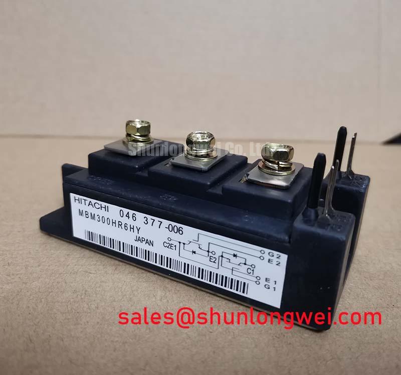
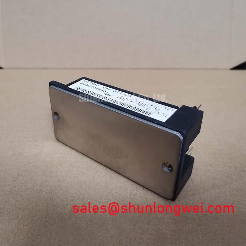
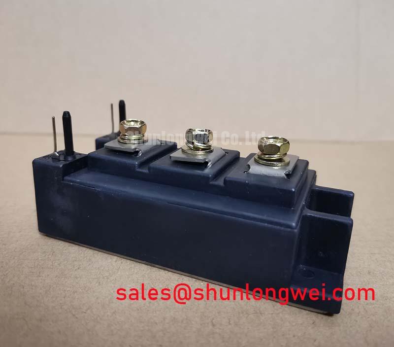
Technical Analysis Around UVP
The primary value proposition of the MBM300HR6HY lies in its optimized balance between conduction efficiency and rugged switching performance. Operating at 1700V, power devices face extreme electrical stresses that can trigger latch-up. By utilizing advanced silicon processing, this module maintains a low typical collector-emitter saturation voltage ($V_{CE(sat)}$) of 2.7V. This minimizes on-state conduction losses during heavy-duty cycles.
Effective thermal management is essential to prevent common igbt failures caused by localized hotspots. The MBM300HR6HY incorporates isolated baseplates that lower the junction-to-case thermal resistance ($R_{th(j-c)}$). You can visualize thermal resistance as a narrow pipe restricting water flow. A lower thermal resistance acts like a wider pipe, allowing heat to escape quickly into the heatsink. This prevents thermal runaway and extends the system operating lifetime.
Furthermore, managing the gate charge ($Q_g$) is vital to avoid high switching losses. The MBM300HR6HY displays a highly controlled gate-emitter charge transition. This profile reduces the driver circuit load, allowing cleaner switching transitions. It also limits electromagnetic interference (EMI) during high-frequency operation.
Optimized Application Scenarios
This IGBT Module configuration is highly suited for several heavy-industrial setups:
- Industrial AC Motor Drives: The 1700V rating easily accommodates standard 460V to 690V line utility inputs, providing sufficient safety margin against line voltage surges.
- Wind Power Inverters: Excellent power cycling capability enables the module to handle the variable thermal loading typical of wind energy conversion.
- Traction Auxiliary Converters: High vibration resistance and robust terminal connections prevent mechanical failures in transit environments.
- Uninterruptible Power Supplies (UPS): Low conduction losses ensure high system efficiency under continuous duty cycles.
Best-Fit Conclusion: Optimized for high-power industrial applications requiring 1700V isolation and continuous 300A switching reliability under harsh thermal environments.
Key Specifications Parameter Table
| Absolute Maximum Ratings ($T_c = 25^circtext{C}$ unless otherwise specified) | ||
|---|---|---|
| Collector-Emitter Voltage | $V_{CES}$ | 1700 V |
| Gate-Emitter Voltage | $V_{GES}$ | ±20 V |
| Continuous Collector Current | $I_C$ | 300 A |
| Electrical Characteristics (Typical Values) | ||
| Collector-Emitter Saturation Voltage | $V_{CE(sat)}$ | 2.7 V (at $I_C = 300text{A}$, $T_j = 125^circtext{C}$) |
| Gate-Emitter Threshold Voltage | $V_{GE(th)}$ | 6.0 V |
| Thermal Characteristics | ||
| Thermal Resistance (Junction-to-Case) | $R_{th(j-c)}$ | 0.06 K/W (IGBT part) |
| Isolation Voltage | $V_{isol}$ | 4000 V AC (1 minute) |
Engineer FAQ
Q1: How do you calculate the required heatsink thermal resistance for the MBM300HR6HY?
A1: Use the thermal circuit formula $R_{th(c-s)} + R_{th(s-a)} = (T_{j,max} – T_a) / P_{loss} – R_{th(j-c)}$. Ensure total losses ($P_{loss}$) are calculated using conduction and switching losses from your gate drive profile. Keep junction temperature below 125°C for optimal reliability.
Q2: How can users suppress collector-emitter voltage spikes during turn-off transients?
A2: Minimize stray inductance in the DC busbar layout. Additionally, use an appropriately sized snubber capacitor directly across the module terminals. A gate resistor ($R_g$) can also be tuned to control the turn-off rate.
Q3: Does the MBM300HR6HY require a negative gate turn-off voltage?
A3: Yes. Using a gate drive voltage of -15V during the off-state is recommended to prevent parasitic turn-on caused by high transient voltage transitions through the Miller capacitance.
The MBM300HR6HY power module offers a highly robust switching platform for industrial energy conversion. By combining high voltage endurance with low thermal resistance, it allows power electronics engineers to construct compact, efficient, and long-lasting converter topologies.