Mitsubishi PM300CL1A060 IGBT Module: A Technical Review
Mitsubishi PM300CL1A060 IGBT Module Technical Review
High-Current 600V/300A IGBT Module for Industrial Inverters
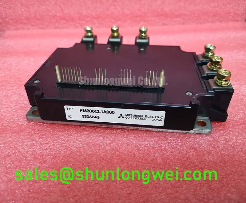
The Mitsubishi PM300CL1A060 is a high-power IGBT module engineered for demanding power conversion applications. It integrates six IGBTs in a half-bridge configuration, providing a robust foundation for three-phase inverter designs. This module’s primary value lies in its high current handling capability combined with effective thermal performance, enabling reliable operation in high-stress industrial environments.
- Core Specifications: 600V | 300A | VCE(sat) (typ) 2.2V
- Key Advantages: High current density, simplified thermal management through an isolated baseplate.
- Design Consideration: Understanding the module’s thermal resistance from junction to case is crucial for effective heatsink selection and ensuring long-term reliability.
Download the Official PM300CL1A060 Datasheet (PDF)

Technical Analysis for System Integration
The PM300CL1A060 is built around Mitsubishi’s trench-gate IGBT technology, which balances conduction and switching losses. A key parameter for engineers is the collector-emitter saturation voltage (VCE(sat)), specified at a typical value of 2.2V at the nominal current. This low VCE(sat) directly reduces the power dissipated as heat during the on-state, which is critical in high-current applications. Lower conduction losses ease the burden on the cooling system and contribute to overall system efficiency.
Another critical parameter is the thermal resistance, Rth(j-c), which is specified per IGBT. Think of thermal resistance as the width of a pipe for heat; a lower value means heat can flow more easily from the active silicon chip to the module’s baseplate. For the PM300CL1A060, the specified thermal resistance allows engineers to accurately calculate the junction temperature under various load conditions, forming the basis of a reliable thermal management strategy. Proper thermal design is essential to prevent the device from exceeding its maximum junction temperature of 150°C.
Optimized Application Scenarios
The specifications of the PM300CL1A060 make it a strong candidate for several high-power industrial applications:
- Variable Frequency Drives (VFDs): Its 300A rating is well-suited for controlling large AC motors in applications like industrial conveyors, pumps, and fans, where robust performance is essential.
- Servo Drives: For high-power servo applications requiring precise motor control, the module provides the necessary current capacity and switching performance.
- Welding Power Supplies: The module’s ability to handle high current pulses makes it suitable for the inverter stage of industrial welding equipment.
- Uninterruptible Power Supplies (UPS): In large-scale UPS systems, this IGBT can be used in the inverter stage to ensure a stable and reliable AC output during power outages.
This module is best matched for applications requiring a balance of high current capability and straightforward thermal design in the sub-20 kHz switching frequency range.


Key Specifications of the PM300CL1A060
| Absolute Maximum Ratings (Tj=25°C unless otherwise noted) | |
|---|---|
| Collector-Emitter Voltage (VCES) | 600V |
| Collector Current (IC) | 300A |
| Collector Power Dissipation (PC) | 1388W |
| Operating Junction Temperature (Tj) | -40 to +150°C |
| Electrical Characteristics (Tj=25°C) | |
| Collector-Emitter Saturation Voltage (VCE(sat)) (Typ) | 2.2V (at IC = 300A) |
| Gate-Emitter Threshold Voltage (VGE(th)) | 5.0 ~ 8.0V |
| Input Capacitance (Cies) (Typ) | 36nF |
| Thermal & Mechanical Characteristics | |
| Thermal Resistance (Rth(j-c)) per IGBT | 0.09 °C/W |
| Isolation Voltage (Viso) | 2500V (AC, 1 minute) |
| Mounting Torque (Main Terminals) | 3.5 – 4.5 N·m |
Engineer’s FAQ for the PM300CL1A060
1. What are the primary thermal considerations when designing with this module?
The main goal is to keep the junction temperature (Tj) below the 150°C maximum rating. To do this, calculate the total power loss (conduction + switching) and use the specified Rth(j-c) of 0.09 °C/W to determine the required heatsink-to-ambient thermal resistance. A high-quality thermal interface material (TIM) between the module baseplate and the heatsink is critical for effective heat transfer.
2. What are the recommended gate drive voltage levels for this IGBT?
The datasheet specifies the gate-emitter threshold voltage (VGE(th)) range is between 5.0V and 8.0V. However, for full enhancement and to minimize conduction losses, a positive gate voltage of +15V is typically recommended for turn-on. For secure turn-off and improved noise immunity, a negative gate voltage (e.g., -5V to -15V) is advised. Always refer to the datasheet’s gate drive characteristic curves for precise design.
3. How critical is the mounting torque specification?
Adhering to the recommended mounting torque (3.5 – 4.5 N·m for mounting screws) is extremely important. Insufficient torque can lead to poor thermal contact with the heatsink, causing overheating. Excessive torque can warp the module’s baseplate, creating gaps that also degrade thermal performance and can potentially damage the internal structure over time. Use a calibrated torque wrench for installation.
Enabling Robust High-Power Systems
The Mitsubishi PM300CL1A060 provides a direct path for implementing high-current power stages. Its established trench-gate technology and standard industrial package offer a proven solution for engineers developing or maintaining systems in the 100-200 kW power class. By focusing on proper gate drive and effective thermal management, this module facilitates the creation of efficient and reliable industrial power converters.