SKM75GB128D IGBT Module: A Technical Analysis for High-Reliability Power Systems
SKM75GB128D SEMIKRON IGBT Module | 1200V 75A SEMITRANS 2
Introduction and Core Highlights
The SEMIKRON SKM75GB128D is a dual IGBT module engineered for robust performance and high reliability in demanding power conversion systems. Its core value stems from the integration of proven Non-Punch-Through (NPT) IGBT technology with a soft-recovery CAL (Controlled Axial Lifetime) freewheeling diode. This combination delivers a durable solution that simplifies thermal management and mitigates electromagnetic interference (EMI), making it a stable component for industrial drive and power supply applications.
- Core Specifications: 1200V | 75A | VCE(sat) (typ) 2.15V
- Key Advantages: High short-circuit capability, Low switching-induced EMI
- Design Focus: Enables simplified, reliable inverter designs with enhanced thermal safety margin.
Download the Official SKM75GB128D Datasheet (PDF)
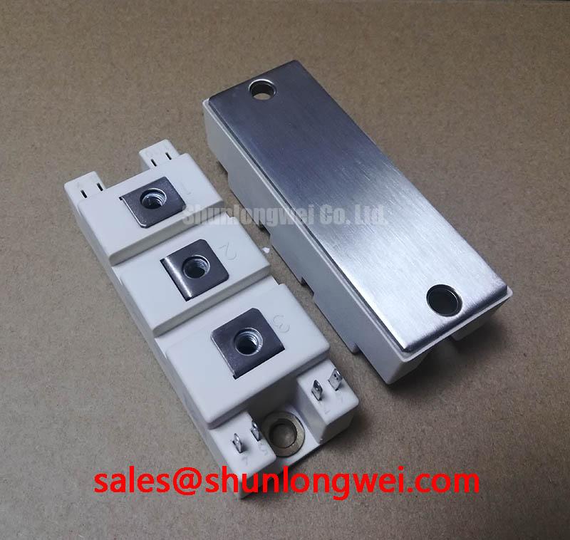

Technical Analysis for System Integration
The engineering value of the SKM75GB128D is rooted in its robust silicon and thoughtful integration. The module utilizes NPT IGBT technology, which is inherently rugged. This is quantitatively demonstrated by its short-circuit withstand time (tsc) of 10 µs at a junction temperature of 125°C. This specific rating provides a critical safety margin in applications like motor drives, where fault conditions such as a locked rotor can cause sudden, high current spikes. This durability reduces the likelihood of catastrophic failure, a key consideration for systems deployed in industrial environments.
Complementing the IGBT is the integrated CAL freewheeling diode. Its primary engineering benefit is its “soft” recovery characteristic. During the turn-off phase of the opposing IGBT in the half-bridge, a diode with abrupt recovery can cause significant voltage overshoot and ringing, generating EMI that can interfere with control circuits. The CAL diode’s soft recovery minimizes these oscillations. This allows engineers to design systems with smaller, less costly snubber circuits and simplifies EMI filtering, contributing to a more compact and cost-effective final product. Further insights into the role of diodes can be found in our analysis of soft-recovery diodes and IGBT performance.
Effective thermal management is directly addressed by the module’s specified thermal resistance. The datasheet specifies a maximum thermal resistance from junction to case (Rth(j-c)) of 0.45 K/W for the IGBT and 0.8 K/W for the diode. One can visualize thermal resistance as the width of a pipe for heat; a lower value signifies a wider pipe, allowing heat to flow away from the silicon more easily. These defined values are critical inputs for engineers calculating heatsink requirements to ensure the maximum operating junction temperature of 150°C is not exceeded. The module also features an isolated baseplate, providing 2500V of isolation, which simplifies assembly by allowing multiple modules to be mounted on a single, non-isolated heatsink.

Optimized Application Scenarios
The technical characteristics of the SKM75GB128D make it a strong candidate for a range of medium-power, high-reliability applications:
- AC Inverter Drives: The module’s half-bridge configuration is the fundamental building block for three-phase inverters. Its robust SCSOA is ideal for handling the demanding current profiles of motor control.
- Uninterruptible Power Supplies (UPS): The high reliability and 1200V breakdown voltage provide the necessary safety margins for line-interactive and online UPS systems.
- Industrial Switched Mode Power Supplies (SMPS): For high-power DC-DC converters or power factor correction (PFC) stages, the module offers a balance of switching performance and conduction efficiency.
- Welding Equipment: The module’s ability to handle a repetitive peak collector current of 150A makes it suitable for the pulsed power demands of modern welding inverters.
This module is best suited for systems operating at switching frequencies up to 8 kHz where reliability and thermal stability are primary design criteria.
Key Specification Parameters
| Absolute Maximum Ratings (per IGBT / Diode) | |
|---|---|
| Collector-Emitter Voltage (VCES) | 1200 V |
| DC Collector Current (IC) @ Tc=80°C | 55 A |
| Repetitive Peak Collector Current (ICRM) | 150 A |
| Total Power Dissipation (Ptot) @ Tc=25°C | 330 W |
| Operating Junction Temperature (Tj) | -40 to +150 °C |
| Electrical Characteristics (Tj = 25°C unless otherwise specified) | |
| Collector-Emitter Saturation Voltage (VCE(sat)) @ IC=75A | 2.15 V (typ.), 2.5 V (max.) |
| Gate-Emitter Threshold Voltage (VGE(th)) | 4.5 V (min.), 5.5 V (typ.), 6.5 V (max.) |
| Diode Forward Voltage (VF) @ IF=75A | 2.1 V (typ.), 2.5 V (max.) |
| Thermal Resistance, Junction to Case (Rth(j-c)), IGBT | 0.45 K/W (max.) |
| Thermal Resistance, Junction to Case (Rth(j-c)), Diode | 0.8 K/W (max.) |
Engineer’s FAQ
- How does the thermal resistance of the SKM75GB128D influence heatsink selection?
- The thermal resistance from junction to case (Rth(j-c)) is a critical parameter for thermal design. Using the maximum values of 0.45 K/W for the IGBT and 0.8 K/W for the diode, along with the calculated power losses, you can determine the maximum allowable thermal resistance for your heatsink (Rth(c-s)) and thermal interface material to keep the junction temperature below the 150°C maximum limit under worst-case operating conditions.
- What are the recommended mounting torque specifications for this module?
- According to the datasheet, the recommended mounting torque for the M6 terminal screws is 3-5 Nm, and for the M5 mounting screws, it is also 3-5 Nm. Applying the correct torque is essential to ensure good thermal contact and prevent mechanical stress on the module. For more details on this topic, see our guide on the critical role of IGBT terminal torque.
- What is the primary benefit of the NPT technology used in this IGBT?
- The Non-Punch-Through (NPT) IGBT structure provides excellent ruggedness and a wide Safe Operating Area (SOA). This results in a high short-circuit withstand capability (10 µs for this module) and stable performance across a wide temperature range, enhancing overall system reliability.
- What is the recommended gate-emitter voltage range?
- The datasheet specifies a gate-emitter threshold voltage (VGE(th)) between 4.5V and 6.5V. For driving the IGBT, a gate voltage of +15V is typical for turn-on. While a 0V gate voltage can be used for turn-off, applying a small negative voltage (e.g., -8V to -15V) is often recommended to improve noise immunity and prevent parasitic turn-on.
Enabling Robust Power Designs
The SKM75GB128D IGBT module provides a well-balanced combination of electrical performance, thermal stability, and proven ruggedness. By integrating reliable NPT silicon and soft-recovery diodes within a standard isolated package, it offers a straightforward path to developing durable and efficient power conversion systems for a variety of industrial applications. For more insights on IGBT technology choices, explore our comparison of PT and NPT structures.