Technical Review of the Toshiba MG50Q6ES50 1200V 50A IGBT Module
MG50Q6ES50: Toshiba 1200V 50A Six-IGBT Module
Integrated Three-Phase Inverter for Motor Control Applications
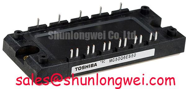
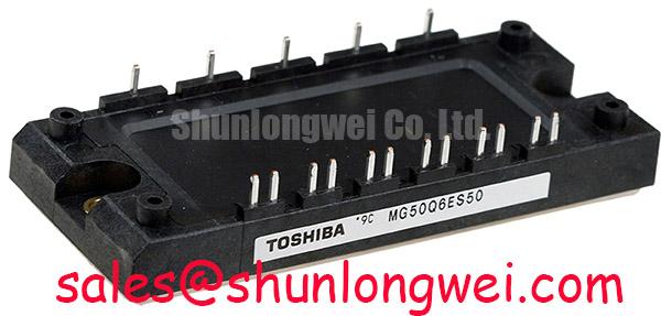
The Toshiba MG50Q6ES50 is an N-Channel IGBT module that integrates a complete three-phase bridge into a single, electrically isolated package. This device is engineered to streamline the design of power conversion systems by combining six 1200V, 50A IGBTs with six corresponding free-wheeling diodes. The primary advantage lies in its functional integration, which simplifies PCB layout, reduces component count, and minimizes assembly complexity in medium-power applications. This integrated approach is particularly effective for developing compact and reliable variable frequency drives.
- Core Specifications: 1200V | 50A | 2500V Isolation
- Key Advantages: Simplifies three-phase bridge design, ensures robust electrical isolation.
Download Official Datasheet (PDF)

Technical Analysis
The core value of the MG50Q6ES50 module is its six-in-one configuration. By housing a full three-phase inverter stage in a single component, engineers can avoid the complex task of matching six individual IGBTs and six diodes. This not only simplifies procurement and inventory but also helps to minimize parasitic inductance, which is a common challenge in designs using discrete components. Lower system inductance contributes to reduced voltage overshoots during high-speed switching, a key factor in improving overall system reliability. For more insights on this topic, consider reading about the impact of parasitic inductance on IGBT switching performance.
Effective thermal management is critical for reliability in power electronics. The MG50Q6ES50 datasheet specifies a maximum thermal resistance from junction-to-case (Rth(j-c)) of 0.45 K/W for each IGBT. This value can be thought of as the width of a pipe for heat; a lower value means heat can escape more easily from the semiconductor junction to the heatsink. A defined thermal resistance allows engineers to perform precise calculations for heatsink selection, ensuring the junction temperature stays within its safe operating limit of 150°C. Furthermore, the module’s baseplate is electrically isolated from all terminals, rated to withstand 2500V (AC for 1 minute), which simplifies mounting procedures and enhances safety by preventing accidental shorts to the chassis.
Optimized Application Scenarios
The architecture of the MG50Q6ES50 is well-suited for several mid-power industrial applications:
- AC Motor Drives: The module’s three-phase bridge is the fundamental building block for Variable Frequency Drives (VFDs). Its 50A current rating makes it suitable for controlling three-phase induction motors typically in the 15 kW to 22 kW (20 to 30 HP) class, depending on the line voltage.
- Uninterruptible Power Supplies (UPS): The robust 1200V rating provides a significant safety margin for the DC-AC inverter stage in UPS systems connected to 380V or 480V AC mains.
- Welding Power Supplies: The module can serve as the main switching element in inverter-based welders, where precise control of the power output is required.
- General Purpose Inverters: For any application requiring conversion from DC to three-phase AC, this module offers a compact, pre-validated power stage that accelerates development.
This module is best matched for systems needing a reliable, integrated three-phase inverter stage for loads up to approximately 30 kVA.
Key Specifications of the MG50Q6ES50
| Absolute Maximum Ratings (Ta = 25°C) | |
|---|---|
| Collector-Emitter Voltage (V_CES) | 1200 V |
| Gate-Emitter Voltage (V_GES) | ±20 V |
| Collector Current (DC, I_C) | 50 A (at Tc = 80°C) |
| Collector Power Dissipation (P_C) | 280 W (per IGBT) |
| Operating Junction Temperature (T_j) | -40 to 150 °C |
| Isolation Voltage (V_isol) | 2500 V (AC, 1 minute) |
| Electrical and Thermal Characteristics (Tj = 125°C unless otherwise noted) | |
| Collector-Emitter Saturation Voltage (V_CE(sat)) | 2.7 V (Max) at I_C = 50 A |
| Diode Forward Voltage (V_EC) | 2.5 V (Max) at I_E = 50 A |
| Turn-On Time (t_on) | 0.3 µs (Typ) |
| Turn-Off Time (t_off) | 0.5 µs (Typ) |
| Thermal Resistance, Junction to Case (Rth(j-c)) – IGBT | 0.45 K/W (Max) |
| Thermal Resistance, Junction to Case (Rth(j-c)) – Diode | 0.83 K/W (Max) |
Engineer’s FAQ
1. What is the primary advantage of using a three-phase IGBT module like the MG50Q6ES50?
The main advantage is design simplification. This single module replaces twelve discrete components (six IGBTs and six diodes), ensuring matched dynamic and static characteristics between the devices. This integration reduces PCB complexity, lowers stray inductance, and shortens assembly time.
2. How do I calculate the heatsink required for this module?
To determine the heatsink requirement, you must first calculate the total power dissipation (conduction losses + switching losses) for your specific operating conditions. Then, use the module’s thermal resistance (Rth(j-c) = 0.45 K/W for the IGBT) and the desired maximum junction temperature (e.g., 125°C for reliability) to calculate the maximum allowable case temperature. The required heatsink thermal resistance can then be determined based on the ambient temperature. A deeper understanding of this can be found in our guide to mastering IGBT thermal design.
3. What gate driver voltage does the MG50Q6ES50 require?
The datasheet specifies a standard gate-emitter voltage (V_GES) of ±20V absolute maximum. For optimal performance, a positive gate voltage of +15V is typically used to ensure the IGBT is fully turned on and achieves the specified low V_CE(sat). A negative voltage (e.g., -5V to -10V) is recommended for turn-off to provide better noise immunity and prevent parasitic turn-on.
4. Does the MG50Q6ES50 include an NTC thermistor for temperature sensing?
No, based on the official circuit diagram in the datasheet, this module does not integrate an NTC thermistor. For applications requiring direct temperature feedback, an external temperature sensor must be mounted close to the module’s baseplate.
By providing a complete and isolated power stage in a single housing, the MG50Q6ES50 enables engineers to focus on system-level control and functionality. Its balanced electrical characteristics deliver a reliable foundation for building efficient and compact industrial power conversion systems.