2MBI200NB-120 IGBT Module: A Technical Review and Application Guide
2MBI200NB-120 IGBT Module | 1200V 200A Dual Configuration
Introduction to the Fuji Electric 2MBI200NB-120 N-Series Module
The Fuji Electric 2MBI200NB-120 is a 1200V, 200A dual IGBT module from their N-Series, engineered for high-power switching applications. This module’s primary value lies in its balanced design, offering a low collector-emitter saturation voltage (VCE(sat)) and robust thermal performance to enable efficient and reliable power conversion. It integrates two IGBTs in a half-bridge configuration, streamlining the design of compact inverters.
- Core Specifications: 1200V | 200A | VCE(sat) 3.3V max
- Key Advantages: Optimized for reduced total power dissipation and features a square Reverse Bias Safe Operating Area (RBSOA) for enhanced ruggedness.
- Design Focus: Low internal stray inductance contributes to cleaner switching waveforms and reduced voltage overshoot.
For detailed electrical and thermal characteristics, refer to the official 2MBI200NB-120 Datasheet (PDF).
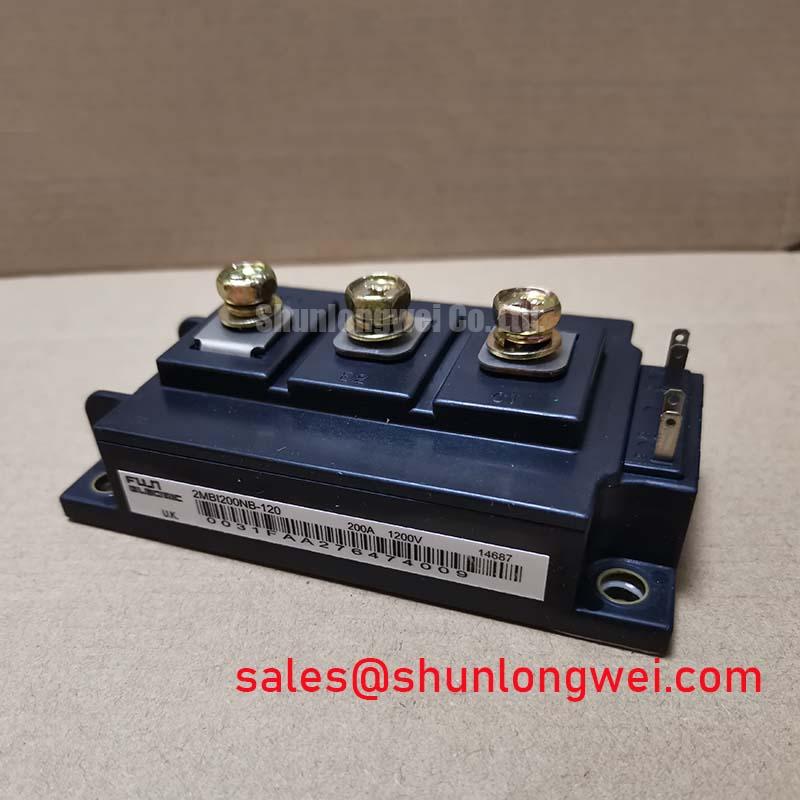
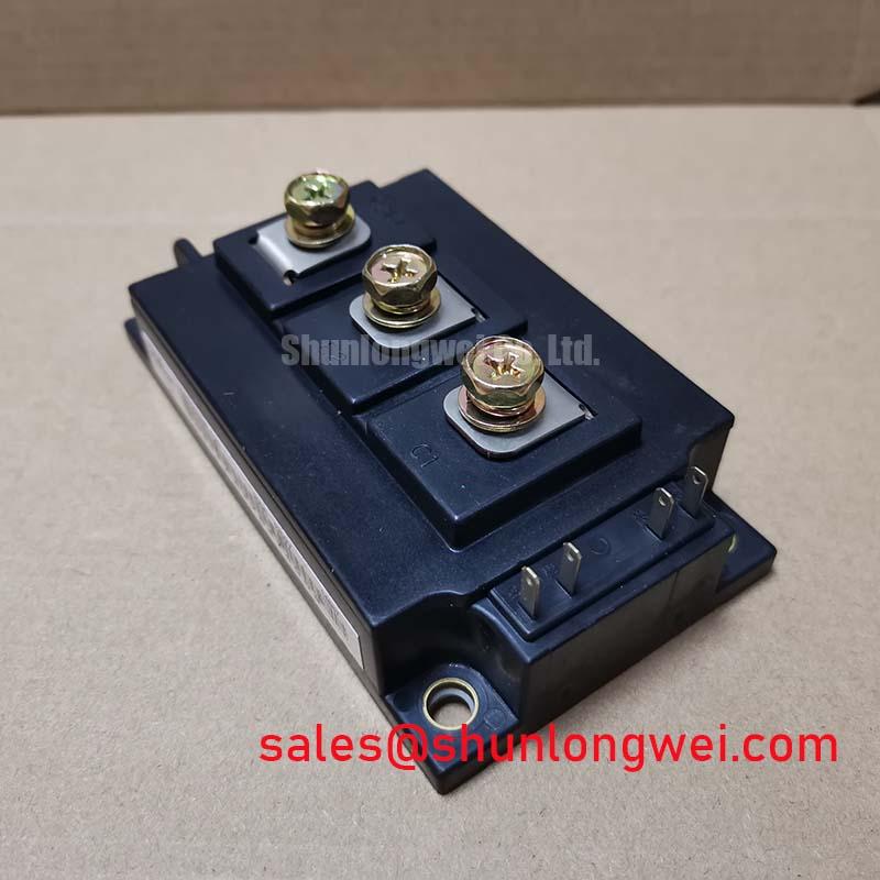
Technical Analysis for System Integration
A critical parameter for system efficiency is the collector-emitter saturation voltage, VCE(sat), which is specified at a maximum of 3.3V at 200A. This value directly dictates the conduction losses during the on-state of the IGBT. A lower VCE(sat) means less power is dissipated as heat, allowing for smaller heatsinks and potentially higher power density in the final application. This characteristic is a cornerstone of the quest for lower IGBT VCE(sat) and improved system efficiency.
The thermal resistance from junction to case (Rth(j-c)) for the IGBT is documented as 0.085 °C/W maximum. This value can be thought of like the width of a pipe for heat flow; a lower number signifies a wider pipe, allowing heat to escape more effectively from the active semiconductor junction to the module’s baseplate. Efficient heat extraction is fundamental for reliability, as it keeps the junction temperature (Tj) within its maximum limit of 150°C, a key factor in preventing component failure. Proper IGBT thermal design is therefore essential for long-term performance.

Optimized Application Scenarios
The 2MBI200NB-120 is well-suited for a range of high-power industrial applications where efficiency and durability are paramount.
- Inverters for Motor Drives: The module’s robust current handling (200A continuous, 400A pulsed) and fast-switching freewheeling diode (FWD) with a reverse recovery time (trr) of 0.35 µs make it highly suitable for controlling AC and DC motors.
- Uninterruptible Power Supplies (UPS): Its low conduction losses minimize heat generation, improving the overall efficiency and reliability of UPS systems that must operate continuously.
- Welding Machines: The square RBSOA ensures the device can withstand the demanding switching conditions and high transient voltages often encountered in welding power sources.
With its 1200V blocking voltage and 200A current capability, this module is an excellent fit for three-phase inverters operating from 480-600V AC lines.
Key Specifications of the 2MBI200NB-120
| Absolute Maximum Ratings (Tc=25°C) | ||
|---|---|---|
| Collector-Emitter Voltage (VCES) | 1200 V | |
| Continuous Collector Current (IC) | 200 A | |
| 1ms Pulsed Collector Current (IC pulse) | 400 A | |
| Max. Power Dissipation (PC) | 1500 W | |
| Operating Junction Temperature (Tj) | +150 °C | |
| Electrical and Thermal Characteristics (Tj=25°C) | ||
| Collector-Emitter Saturation Voltage (VCE(sat)) @ IC=200A | 3.3 V (Max) | |
| Gate-Emitter Threshold Voltage (VGE(th)) | 4.5 V (Min) / 7.5 V (Max) | |
| Thermal Resistance, Junction-to-Case (Rth(j-c)) – IGBT | 0.085 °C/W (Max) | |
| Thermal Resistance, Junction-to-Case (Rth(j-c)) – Diode | 0.18 °C/W (Max) | |
Engineer’s Frequently Asked Questions
1. What is a primary consideration for the thermal design using the 2MBI200NB-120?
The key is managing heat extraction based on the thermal resistance values. With an Rth(j-c) of 0.085 °C/W for the IGBT and 0.18 °C/W for the diode, the heatsink and thermal interface material must be selected to keep the junction temperature well below the 150°C maximum under worst-case operating load and ambient temperature conditions.
2. What are the recommended mounting torque settings for this module?
The datasheet specifies a mounting screw torque of 3.5 N·m (M5 or M6 screws) and a terminal screw torque of 4.5 N·m (M6). Applying the correct torque is critical to ensure low thermal resistance to the heatsink and reliable electrical connections without causing mechanical stress to the module.
3. What are the gate drive voltage requirements?
The module specifies a maximum gate-emitter voltage (VGES) of ±20V. The gate-emitter threshold voltage (VGE(th)) ranges from 4.5V to 7.5V. A standard gate drive voltage, such as +15V for turn-on and -8V to -15V for turn-off, is typically used to ensure full enhancement and prevent unintended turn-on due to noise, a topic explored in enhancing IGBT noise immunity.
Enabling Efficient Power System Design
The 2MBI200NB-120 module provides a robust and thermally efficient foundation for industrial power conversion systems. Its combination of low conduction losses, durable construction, and well-defined switching characteristics allows engineers to develop compact, high-performance inverters and power supplies that meet demanding operational requirements.