FF200R12KT4 IGBT Module: A Comprehensive Technical Analysis
“`html
FF200R12KT4 IGBT Module: 1200V 200A Technical Analysis
Introduction and Core Highlights
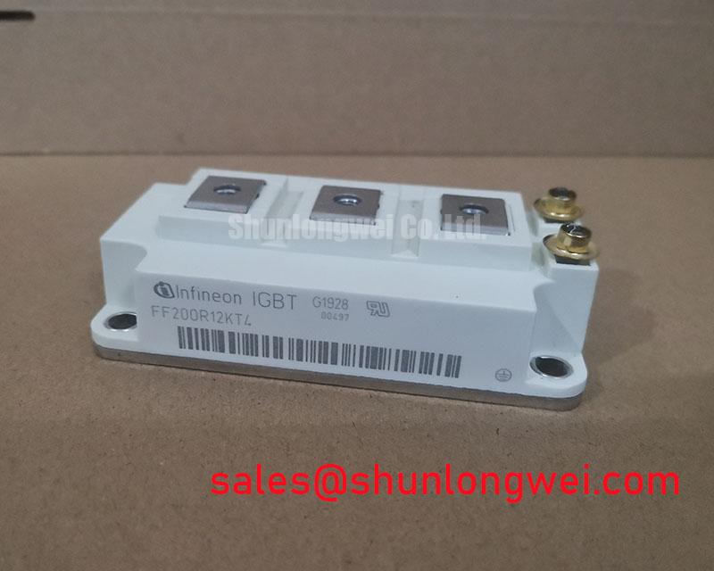
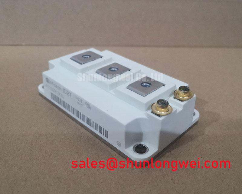
The Infineon FF200R12KT4 is an EconoPACK™+ IGBT module that provides a highly effective balance between conduction and switching losses, leveraging proven Trench/Fieldstop IGBT3 technology. This module is engineered for reliability in high-power converter systems. Its electrical characteristics and thermal performance offer a solid foundation for robust and efficient designs, directly addressing the challenge of managing power density and system costs. For detailed specifications, refer to the official documentation.
- Core Specifications: 1200V | 200A | VCE(sat) (typ.) 1.70V
- Key Advantages: Low conduction losses reduce cooling requirements, and the integrated NTC thermistor simplifies thermal management.
- Design Application: Optimized for three-phase inverter topologies in motor control and power conversion systems.
Download the Official FF200R12KT4 Datasheet (PDF)
Technical Analysis of Core Features
The engineering value of the FF200R12KT4 is rooted in its specific combination of silicon technology and package design. The module’s low collector-emitter saturation voltage (VCE(sat)) of 1.70V at its nominal current is a direct result of the TRENCHSTOP™ IGBT3 technology. This parameter is crucial for system efficiency. Think of VCE(sat) as a measure of friction for electrical current; a lower value means less energy is converted into waste heat during the ‘on’ state. This directly translates to reduced power dissipation, allowing for smaller heatsinks and potentially higher power density in the final application.
Complementing the IGBT is the integrated Emitter Controlled HE freewheeling diode. Its “soft” recovery characteristic is critical for managing voltage overshoots and reducing electromagnetic interference (EMI) during the IGBT’s turn-on event. This controlled behavior minimizes stress on the entire power circuit, contributing to greater system reliability and potentially simplifying the requirements for external snubber circuits. The module also includes an integrated NTC thermistor, providing a direct and reliable method for monitoring operating temperature, a key factor in proactive thermal management and system protection.

Optimized Application Scenarios
The specifications of the FF200R12KT4 make it a strong candidate for several demanding power conversion applications:
- Variable Frequency Drives (VFDs): The module’s balance of switching and conduction losses is well-suited for the typical operating frequencies of industrial motor drives. Its thermal efficiency helps maintain reliability in enclosed industrial environments.
- Solar Inverters: In large-scale solar installations, the 1200V blocking voltage and high current capability enable efficient DC-AC conversion, while the low VCE(sat) maximizes energy harvest by minimizing losses.
- Uninterruptible Power Supplies (UPS): The module’s robust Safe Operating Area (SOA) and ability to handle high currents ensure reliable operation during critical power backup and conditioning tasks.
- Welding Power Supplies: The module can effectively handle the pulsed power demands characteristic of welding applications, where controlled switching and thermal stability are essential for performance.
Based on its current rating and thermal performance, this module is an optimal match for three-phase inverter systems designed for power levels up to 90 kW.
Key Specification Parameters for FF200R12KT4
| Parameter | Value | |
|---|---|---|
| Absolute Maximum Ratings | ||
| Collector-Emitter Voltage (V_CES) | 1200 V | |
| Continuous Collector Current (I_C nom) | 200 A | |
| Operating Junction Temperature (T_vj op) | -40 to +150 °C | |
| IGBT Characteristics (T_vj = 25°C unless otherwise specified) | ||
| Collector-Emitter Saturation Voltage (V_CE sat, typ. at I_C=200A, T_vj=125°C) | 1.70 V | |
| Gate-Emitter Threshold Voltage (V_GE(th)) | 5.0 V to 6.5 V | |
| Thermal Characteristics | ||
| Thermal Resistance, Junction-to-Case (R_thJC) per IGBT | max. 0.098 K/W | |
| Thermal Resistance, Case-to-Heatsink (R_thCH) | typ. 0.005 K/W | |
Engineer’s FAQ
1. What is the maximum recommended gate-emitter voltage for driving the FF200R12KT4?
The datasheet specifies the absolute maximum gate-emitter voltage as ±20V. For proper operation, a positive gate voltage (V_GEon) of +15V is typically used for turn-on, and a negative voltage between -8V and -15V is recommended for a secure turn-off, which can improve noise immunity.
2. What are the critical thermal resistance values for heatsink calculation?
For thermal design, two key values from the datasheet are essential: the maximum thermal resistance from junction-to-case (R_thJC) at 0.098 K/W per IGBT, and the typical thermal resistance from case-to-heatsink (R_thCH) at 0.005 K/W. These figures are the basis for calculating total power dissipation and selecting an appropriate cooling solution.
3. Are there specific mounting considerations for the EconoPACK™+ package?
Yes. To ensure optimal thermal transfer and mechanical stability, it is critical to follow the manufacturer’s recommendations. The datasheet specifies a mounting torque of 3.0 – 6.0 Nm for the M5 mounting screws. Using a thermal interface material (TIM) with a recommended thickness is also necessary to minimize the case-to-heatsink thermal resistance.
4. Does the FF200R12KT4 support parallel operation?
While the datasheet does not explicitly detail parallel operation procedures, connecting IGBT modules in parallel requires careful layout to ensure symmetrical current sharing. Factors like a positive temperature coefficient of VCE(sat) are beneficial for paralleling, but a dedicated gate drive design and busbar symmetry are critical. Consultation of Infineon’s application notes on IGBT paralleling is recommended for such designs.
Concluding Statement
The FF200R12KT4 IGBT module offers a reliable and efficient component choice for power electronics engineers. By integrating proven IGBT3 silicon with a thermally efficient EconoPACK™+ package, it provides a direct path to developing powerful and stable converter systems while simplifying the complexities of thermal design and system monitoring.
“`