Powerex PM10RHB120: A Technical Review of the 1200V/10A Dual IGBT Module
Powerex PM10RHB120 1200V/10A Dual IGBT Module
Introduction and Core Highlights
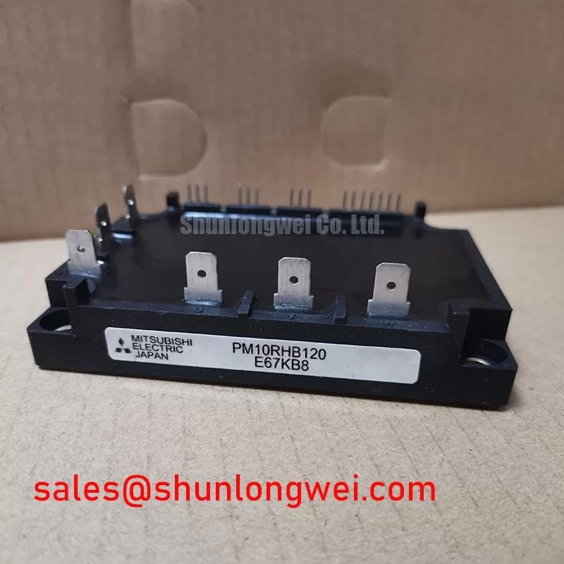
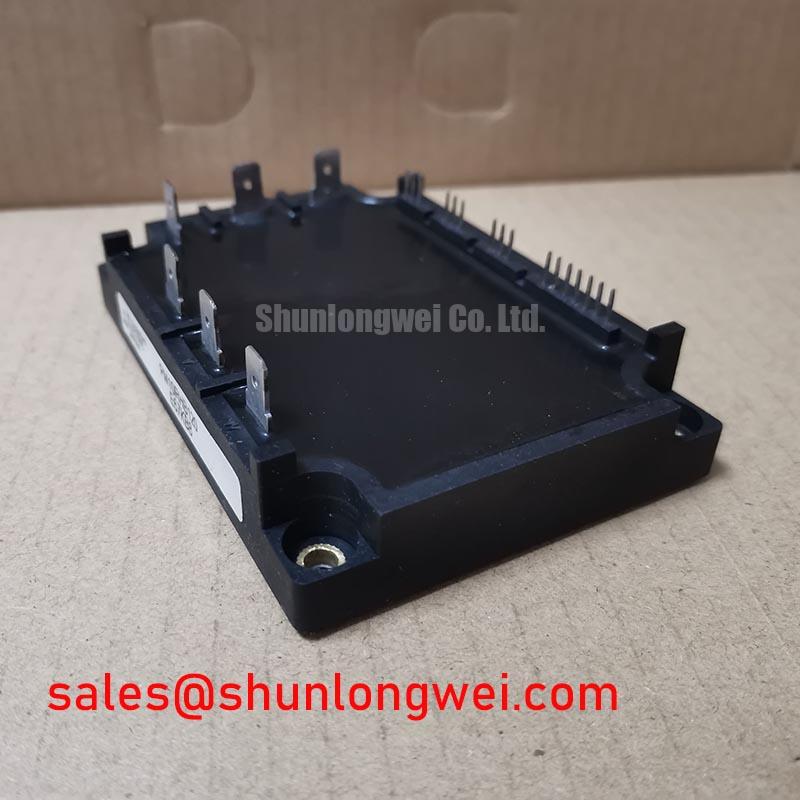
The Powerex PM10RHB120 is a dual IGBTMOD™ power module engineered for constructing efficient and compact half-bridge power stages. This device integrates two 1200V, 10A Insulated Gate Bipolar Transistors (IGBTs) into a single, isolated package, which streamlines the design of motor controls and inverters by reducing component count and simplifying thermal management. Its internal structure is optimized for reliability in general-purpose power switching applications.
- Core Specifications: 1200V | 10A | VCE(sat) 2.7V (Max)
- Key Advantages: Simplifies half-bridge inverter topology, isolated baseplate for easy heatsink mounting.
- Design Consideration: The integrated nature of the PM10RHB120 helps minimize stray inductance compared to discrete solutions.
Download Official Datasheet (PDF)
Technical Analysis of the Dual IGBT Configuration
The primary value of the PM10RHB120 lies in its integrated dual-transistor topology. By housing two IGBTs in a half-bridge configuration within a single module, it provides a fundamental building block for inverter and chopper applications. This arrangement inherently reduces the physical loop area for current, which can lead to lower stray inductance compared to a design using two separate discrete components. Lower inductance is critical for minimizing voltage overshoots during high-speed switching events, thereby enhancing system reliability.
Understanding Thermal Performance
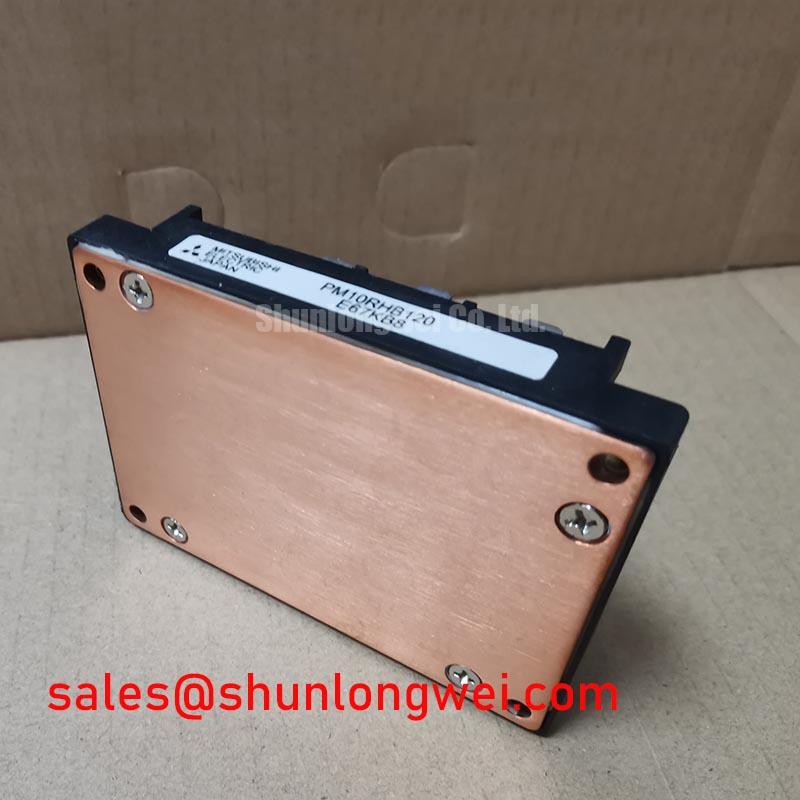
Effective thermal management is crucial for the longevity of any power module. The PM10RHB120 specifies a thermal resistance from junction-to-case (Rth(j-c)) of 1.5°C/W for the IGBT portion. You can think of thermal resistance like the width of a pipe; a lower value signifies a wider pipe, allowing heat to flow more easily from the active silicon die to the module’s case. This parameter is essential for engineers when selecting a heatsink, as it allows for the calculation of the expected junction temperature under specific load conditions, ensuring it remains within the maximum operating limit of 150°C. The module’s isolated baseplate further simplifies this process, as it can be mounted directly to a common heatsink without requiring additional insulating layers. For more information, see our guide on mastering IGBT thermal design.
Optimized Application Scenarios
The specifications of the PM10RHB120 make it a strong candidate for several power conversion tasks:
- Small Variable Frequency Drives (VFDs): The 1200V rating provides a sufficient safety margin for 400/480V AC line applications, while the 10A current capacity is suitable for fractional horsepower motors.
- Uninterruptible Power Supplies (UPS): Its half-bridge configuration is a standard topology used in the inverter stage of online UPS systems.
- Welding Power Supplies: The robust nature of IGBT modules is well-suited for the demanding, pulsed-load conditions found in welding applications.
- General Purpose Inverters: The straightforward design and standard packaging make it a versatile component for various custom power conversion projects.
Its balance of voltage rating, current handling, and integrated half-bridge topology makes it a best match for low-power, three-phase inverter systems.
Key Specification Parameters
| Absolute Maximum Ratings (Tj = 25°C unless otherwise specified) | |
|---|---|
| Collector-Emitter Voltage (Vces) | 1200V |
| Gate-Emitter Voltage (VGES) | ±20V |
| Collector Current (IC) | 10A |
| Collector Current (ICM) (Peak) | 20A |
| Maximum Power Dissipation (PC) | 75W |
| Operating Junction Temperature (Tj) | -40 to 150°C |
| Electrical Characteristics (Tj = 25°C unless otherwise specified) | |
| Collector-Emitter Saturation Voltage (VCE(sat)) (Typ/Max) | 2.2V / 2.7V (at IC = 10A) |
| Gate-Emitter Threshold Voltage (VGE(th)) | 4V to 8V |
| Collector-Emitter Cutoff Current (ICES) | 1mA (at VCE = 1200V) |
| Free Wheel Diode Forward Voltage (VF) (Typ/Max) | 2.0V / 2.5V (at IE = 10A) |
Engineer’s FAQ
What is the primary benefit of the dual IGBT configuration in the PM10RHB120?
The dual IGBT configuration integrates a complete half-bridge circuit into one module. This simplifies PCB layout, reduces the number of required components, and helps minimize parasitic inductance, which is beneficial for reducing voltage overshoot during switching. To understand more about component integration, read our analysis on PIM vs. Discrete IGBTs.
What are the mounting torque specifications for this module?
According to the datasheet, the recommended mounting torque for the M4 mounting screws is 0.98 ~ 1.47 N·m. Applying the correct torque is critical to ensure good thermal contact with the heatsink without causing mechanical stress to the module’s substrate.
How does the VCE(sat) of 2.7V (max) impact my design?
The Collector-Emitter Saturation Voltage (VCE(sat)) is the voltage drop across the IGBT when it is fully turned on. This value is used to calculate conduction losses (Power Loss = VCE(sat) x IC). A VCE(sat) of 2.7V at 10A means you must account for up to 27 watts of conduction loss per IGBT under full load, which directly informs the cooling requirements for your system. For a deeper understanding of this parameter, see this article on the quest for lower VCE(sat).
Does the PM10RHB120 include integrated freewheeling diodes?
Yes, the datasheet confirms that each IGBT is paired with a freewheeling diode (FWD) inside the module. This is standard for half-bridge configurations to provide a path for inductive load current when the IGBT is turned off. The forward voltage (VF) of this diode is specified as 2.5V (max) at 10A.
Enabling Compact Power Designs
The PM10RHB120 module delivers a functionally complete half-bridge power stage in a compact, isolated package. Its datasheet-verified performance provides the necessary data for engineers to implement reliable and thermally stable power circuits for small motor drives, UPS systems, and other general-purpose inverter applications. This integration strategy allows for a streamlined design process and a smaller overall system footprint.