Fuji 6MBP100RA060 IPM: An Integrated Solution for Reliable Motor Control
Fuji 6MBP100RA060 IPM | 600V 100A IGBT Module
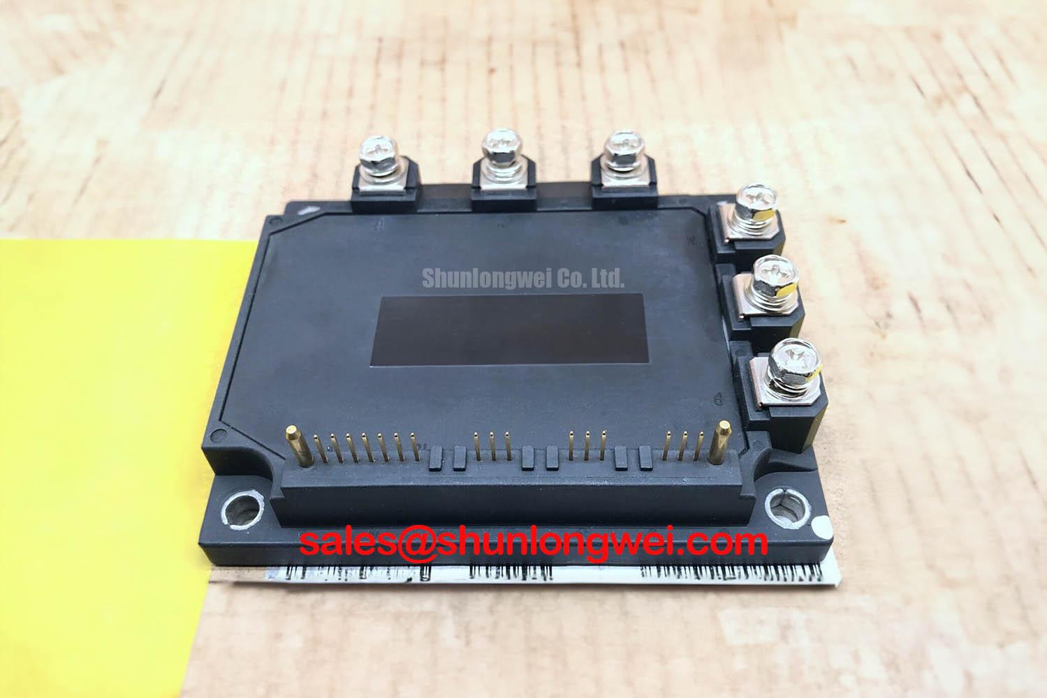
Integrated Power Stage for Reliable Motor Control
The Fuji Electric 6MBP100RA060 is an R-Series Intelligent Power Module (IPM) that combines a three-phase IGBT inverter bridge, freewheeling diodes, and dedicated gate drive and protection circuits into a single, compact package. This level of integration simplifies the design of motor control systems by reducing component count and providing built-in protection against common fault conditions. With its robust construction and integrated thermal and current monitoring, this module is engineered for reliability in demanding industrial applications.
- Core Specifications: 600V | 100A | VCE(sat) 2.7V (Max)
- Key Advantages: Accelerates design cycles with an all-in-one solution. Enhances system reliability with integrated over-current, short-circuit, under-voltage, and over-temperature protection.
- Design Simplification: Eliminates the need for separate gate drivers and complex protection circuitry, reducing PCB complexity and potential points of failure.
Download Official Datasheet (PDF)


Technical Analysis for System Integration
The primary engineering value of the 6MBP100RA060 lies in its high level of integration. By incorporating the six IGBTs and six freewheeling diodes required for a three-phase inverter, along with the necessary gate drive and protection logic, this Intelligent Power Module (IPM) serves as a nearly complete power stage. The datasheet specifies integrated protection for short-circuit (SC), over-current (OC), under-voltage (UV), and over-temperature (OT) events. This integration removes the significant engineering overhead of designing, qualifying, and laying out discrete protection circuits, thereby enhancing overall system reliability and shrinking the development timeline.
Effective thermal management is crucial for the reliability of any power module. The 6MBP100RA060 specifies the thermal resistance from junction to case (Rth(j-c)) for the IGBTs as 0.28°C/W and for the freewheeling diodes (FWD) as 0.45°C/W. Think of thermal resistance as the narrowness of a pipe carrying heat away from the semiconductor. A lower value signifies a wider pipe, allowing heat to dissipate more effectively to the heatsink. The low thermal resistance of this module facilitates efficient heat transfer, which is critical for maintaining the junction temperature below the maximum rating of 150°C and ensuring long-term operational stability.
Optimized Application Scenarios
This module is engineered for applications requiring robust and compact three-phase power control. Its architecture and performance characteristics make it a strong candidate for the following systems:
- AC Motor Drives (VFDs): The 6-in-1 topology is a direct fit for the inverter stage of a Variable Frequency Drive. The 100A current rating supports motors in the multi-kilowatt range, while the integrated protections safeguard against common motor faults.
- Industrial Servo Drives: The fast-acting over-current and short-circuit protection is essential for the dynamic and often unpredictable load profiles found in servo applications, preventing IGBT failures.
- Uninterruptible Power Supplies (UPS): The module’s high reliability and integrated fault management are critical for building dependable UPS systems where uptime is non-negotiable.
With its comprehensive protection and 100A capability, this IPM is best matched for motor control systems up to approximately 45 kW requiring high reliability.
Key Specifications of the 6MBP100RA060
| Parameter | Condition | Value | |
|---|---|---|---|
| Absolute Maximum Ratings (Tc=25°C) | DC Bus Voltage (VDC) | – | 450V |
| Collector-Emitter Voltage (VCES) | – | 600V | |
| Collector Current (IC) | DC | 100A | |
| Junction Temperature (Tj) | – | 150°C | |
| Electrical Characteristics (Tc=Tj=25°C, VCC=15V) | Collector-Emitter Saturation Voltage (VCE(sat)) | IC = 100A | 2.2V (Typ), 2.7V (Max) |
| Forward Voltage of FWD (VF) | -IC = 100A | 2.1V (Typ), 2.7V (Max) | |
| Short Circuit Withstand Time (tsc) | VDC=300V, VCC=15V, Tj=125°C | > 10µs | |
| Thermal Characteristics | Thermal Resistance (IGBT, Rth(j-c)) | Junction-to-Case | 0.28°C/W (Max) |
| Thermal Resistance (FWD, Rth(j-c)) | Junction-to-Case | 0.45°C/W (Max) | |
Engineer’s FAQ for the 6MBP100RA060
1. How does the 6MBP100RA060 protect against overcurrent and short-circuit events?
The module has built-in protection circuits that monitor the collector current of each IGBT. If the current exceeds a predefined threshold (over-current) or rises dramatically in a short-circuit event, the internal gate drive logic immediately shuts down the corresponding IGBTs in a controlled manner to prevent damage. It then sends an alarm signal (via the Valm pin) to the system controller.
2. What are the primary considerations for heatsink mounting?
Proper thermal management is essential. The baseplate of the module must make flat, uniform contact with the heatsink. The datasheet recommends a surface flatness of -50µm to +100µm for the heatsink over the module’s area. A thin, even layer of thermal grease (typically 80-100µm) should be applied to eliminate air voids. Use the specified mounting screw torque (2.5 to 3.5 Nm for M5 screws) to prevent warping the baseplate, which could compromise thermal contact.
3. What is the engineering implication of the VCE(sat) of 2.7V (max)?
The Collector-Emitter Saturation Voltage (VCE(sat)) is the voltage drop across the IGBT when it is fully on. This voltage, multiplied by the current (IC), determines the conduction power loss (P = VCE(sat) * IC). A lower VCE(sat) means lower heat generation during operation. While a typical value of 2.2V is given, thermal calculations for worst-case scenarios should use the maximum value of 2.7V at Tj=125°C to ensure the cooling system is adequate.
4. Do I need an external gate driver for this IPM?
No. The 6MBP100RA060 is an Intelligent Power Module that includes integrated gate drivers. The control logic (terminals Vin) can be driven directly by signals from a microcontroller or DSP (typically 0V for OFF and 5V to VZ for ON), greatly simplifying the control interface design. You only need to provide the appropriate low-voltage power supply (VCC) for the internal logic.
Enabling Robust and Compact Power Designs
This module provides a validated and reliable power stage, allowing engineering teams to focus on system-level control and application-specific features rather than on the complexities of discrete power semiconductor design. The integration of drivers and comprehensive protection within the 6MBP100RA060 facilitates the development of compact, robust, and efficient motor control and power conversion systems with an accelerated path from design to production.