Technical Overview and Applications of the Infineon BSM30GP60 600V 30A IGBT PIM Module
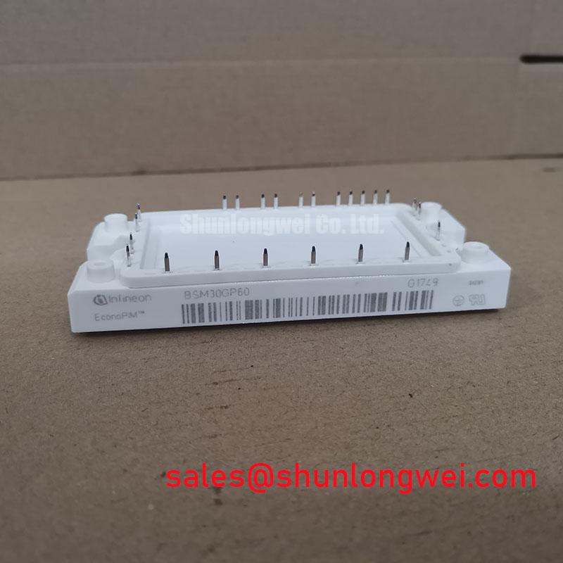
BSM30GP60 Infineon IGBT PIM Module 600V 30A Sixpack
Advanced Integration: The Converter-Inverter-Brake (CIB) Architecture
The BSM30GP60 is a highly integrated Power Integrated Module (PIM) from Infineon (Eupec), engineered using NPT (Non-Punch-Through) Fast IGBT technology. This module consolidates a three-phase bridge rectifier, a sixpack inverter stage, and a dedicated brake chopper into a single compact housing. By centralizing these stages, the module significantly reduces system-level parasitic inductance compared to discrete designs, facilitating cleaner switching waveforms in space-constrained industrial environments.
- Core Ratings: 600V | 30A | Ptot 145W
- Key Advantage: Reduced assembly complexity and improved electromagnetic compatibility (EMC) via integrated power stages.
- Engineering Value: Low $V_{CE(sat)}$ characteristics combined with high ruggedness for high-frequency switching applications.
A common concern for system designers is how the integrated structure affects parasitic inductance. The BSM30GP60 addresses this by optimizing the internal busbar layout, which minimizes voltage overshoots during high $di/dt$ transitions, allowing for a more streamlined snubber circuit design.
Download Official Datasheet (PDF)

Technical Analysis: Thermal Management and Switching Efficiency
The performance of the BSM30GP60 is fundamentally tied to its thermal impedance ($R_{thJC}$) and its low-loss IGBT structure. The NPT technology utilized in this module provides a positive temperature coefficient for the collector-emitter saturation voltage ($V_{CE(sat)}$). This physical property ensures that current is naturally balanced between internal chips during heavy loads, which is vital for preventing localized hotspots and ensuring long-term reliability in power semiconductors.
To understand the engineering significance of the thermal resistance rating, one can visualize $R_{thJC}$ as the diameter of a physical heat pipe. A lower value, such as the 0.85 K/W found in the BSM30GP60’s inverter stage, indicates a “wider pipe” through which thermal energy can flow toward the heatsink. This efficiency allows the device to maintain a stable junction temperature ($T_j$) even during continuous 30A operation at an 80°C case temperature. Proper isolated baseplate mounting is essential to maximize this thermal conductivity.
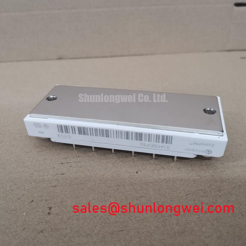
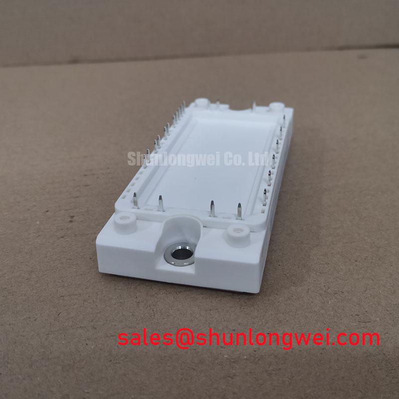
Furthermore, the module includes an integrated NTC thermistor for temperature monitoring. This feature provides real-time feedback to the gate driver or controller, enabling proactive thermal derating. In high-speed switching environments, the impact of parasitic inductance is mitigated by the module’s symmetrical internal routing, which ensures uniform turn-on and turn-off characteristics across all six inverter switches.
Optimized Application Scenarios
- Industrial Motor Drives (VFDs): The integrated converter and inverter stages simplify the power circuit layout for variable frequency drives up to 7.5kW.
- Servo Drive Systems: Fast switching speeds and the integrated brake chopper stage allow for the precise deceleration control required in robotics.
- Uninterruptible Power Supplies (UPS): High integration reduces the number of interconnects, which is critical for maintaining high MTBF (Mean Time Between Failures) in backup power systems.
- Solar Inverters: The 600V rating and low switching losses make it suitable for compact grid-tied or off-grid PV inverters.
Best Match: Ideal for compact 3-phase motor control designs where minimizing PCB footprint and parasitic inductance are primary design constraints.
Key Specification Parameters
| Category | Parameter | Typical Value |
|---|---|---|
| Maximum Ratings | Collector-Emitter Voltage ($V_{CES}$) | 600 V |
| DC Collector Current ($I_C$) | 30 A (@$T_C=80^{circ}C$) | |
| Repetitive Peak Current ($I_{CRM}$) | 60 A | |
| Electrical Characteristics | $V_{CE(sat)}$ (Inverter) | 2.1 V (@$T_j=25^{circ}C$) |
| Gate Threshold Voltage ($V_{GE(th)}$) | 4.5 V to 6.5 V | |
| Switching Energy ($E_{off}$) | 0.9 mJ (Typical) | |
| Thermal Data | Thermal Resistance ($R_{thJC}$) | 0.85 K/W (IGBT stage) |
| Operating Temperature ($T_{vj}$) | -40 to +150 $^{circ}C$ |
Engineer FAQ
Q1: What is the benefit of the integrated brake chopper in the BSM30GP60?
A: It allows for an external braking resistor to be connected directly to the module, enabling the dissipation of regenerative energy during motor deceleration without requiring additional high-power switching components on the PCB.
Q2: Is a negative gate voltage required for turn-off?
A: While the NPT technology is rugged, applying a negative gate voltage (typically -5V to -15V) is recommended in high-noise environments to prevent parasitic turn-on caused by Miller capacitance.
Q3: How should the heatsink mounting be calculated to prevent thermal runaway?
A: You must ensure the sum of $R_{thJC}$, $R_{thCH}$ (case-to-heatsink), and $R_{thHA}$ (heatsink-to-ambient) allows the junction temperature to remain below 125°C under the worst-case continuous load. For detailed calculations, refer to the Infineon VCE(sat) calculation guide.
The BSM30GP60 stands as a robust solution for engineers seeking to balance power density with electrical performance. Its Converter-Inverter-Brake configuration provides the foundational reliability needed for demanding industrial motion control and power conversion designs.