SKiiP 13NAB12T4V1: A Solder-Free 1200V 15A MiniSKiiP PIM Module for Industrial Reliability
SKiiP 13NAB12T4V1 | Semikron 1200V 15A MiniSKiiP PIM Module
Semikron-Danfoss SKiiP 13NAB12T4V1: The Solder-Free PIM Architecture
The SKiiP 13NAB12T4V1 represents a highly integrated 3-phase Power Integrated Module (PIM) designed within the versatile MiniSKiiP 1 package. This module incorporates a 3-phase bridge rectifier, a 3-phase bridge inverter based on Trench IGBT 4 technology, and a dedicated brake chopper. By leveraging Semikron’s proprietary pressure-contact technology, this module eliminates the need for traditional solder joints between the PCB and the power module, directly addressing the primary failure modes associated with thermal cycling fatigue.
- Core Ratings: 1200V | 15A Inverter Current ($T_s = 70^circ C$) | $V_{CE(sat)}$ 1.85V (Typical)
- Engineering Value: Significant reduction in assembly time via single-screw mounting and enhanced lifecycle through spring-contact reliability.
- User Intent: Engineers seeking to understand how pressure-contact modules improve reliability in Variable Frequency Drives (VFD) will find that the solder-free interface removes the risk of joint delamination.
Download Official SKiiP 13NAB12T4V1 Datasheet (PDF)

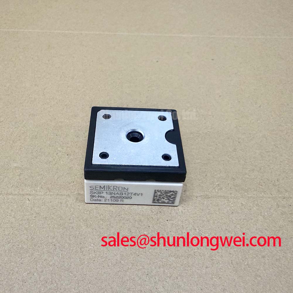
Technical Analysis: Trench IGBT 4 and Spring Contact Synergy
The SKiiP 13NAB12T4V1 utilizes the Trench IGBT 4 (T4) generation, which is optimized for industrial switching frequencies. In 1200V applications, the T4 chip provides a balanced trade-off between switching losses and conduction losses. The typical collector-emitter saturation voltage ($V_{CE(sat)}$) is rated at 1.85V at $T_j = 25^circ C$, rising to 2.25V at $T_j = 150^circ C$. This positive temperature coefficient is a critical parameter for designers implementing IGBT paralleling, as it ensures natural current sharing and prevents thermal runaway within the module’s 3-phase inverter stage.
A distinctive feature of the MiniSKiiP package is the integration of an NTC (Negative Temperature Coefficient) thermistor. This sensor provides real-time feedback of the substrate temperature, allowing the control logic to implement proactive derating or shutdown protocols. For a deep dive into how this protects the silicon, refer to our analysis on integrated NTC for IGBT module safety. The thermal resistance from junction to heatsink ($R_{th(j-s)}$) for the inverter IGBT is 1.45 K/W. To visualize this, consider thermal resistance as the narrowness of a heat-escape path; a lower K/W value indicates a “wider pipe” that allows heat to flow more efficiently away from the die, thereby maintaining the junction temperature ($T_j$) within its 175°C maximum operating limit.
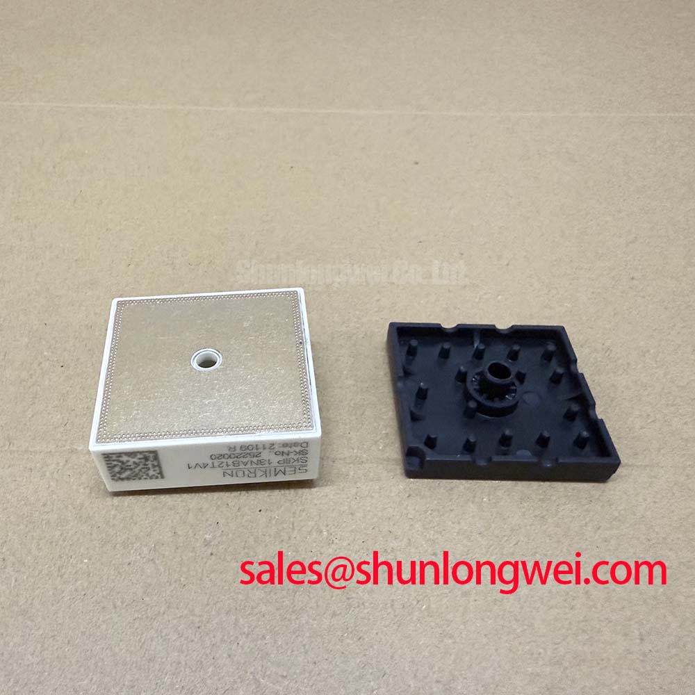
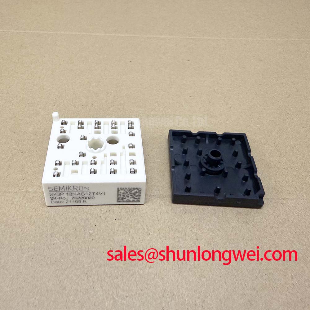
Optimized Industrial Application Scenarios
The architectural choices of the SKiiP 13NAB12T4V1 make it suitable for several specific industrial power electronics categories:
- Small Motor Drives: The integrated 3-phase rectifier and inverter simplify the BOM for drives rated up to approximately 4.0 kW, where PCB space is at a premium.
- Servo Drive Systems: The inclusion of a brake chopper allows for effective management of regenerative energy during rapid motor deceleration, a common requirement in precision motion control.
- Industrial Fan and Pump Control: The Trench gate evolution in this module provides high efficiency at the 4-16 kHz switching frequencies typical of these applications.
- Solar Inverter Strings: Excellent reliability in harsh thermal environments due to the spring-loaded contacts which accommodate mechanical stress better than traditional welded or soldered modules.
The SKiiP 13NAB12T4V1 is a best-match solution for compact inverter designs requiring 1200V isolation and simplified mechanical assembly via solder-free pressure mounting.
Key Technical Specifications
| Category | Parameter | Value (Typical) |
|---|---|---|
| Inverter IGBT | $V_{CES}$ (Collector-Emitter Voltage) | 1200 V |
| $I_C$ (Collector Current at $T_s = 70^circ C$) | 15 A | |
| Rectifier Bridge | $V_{RRM}$ (Repetitive Peak Reverse Voltage) | 1600 V |
| $I_F$ (Forward Current at $T_s = 70^circ C$) | 24 A | |
| Thermal Data | $T_{j(max)}$ (Max Junction Temperature) | 175 °C |
| $R_{th(j-s)}$ (Inverter IGBT) | 1.45 K/W |
Engineer FAQ
Q1: What are the primary advantages of the solder-free spring contacts in the SKiiP 13NAB12T4V1?
A: The spring contacts eliminate the solder interface between the power module and the PCB. This configuration significantly increases power cycling capability because there are no solder joints to develop micro-cracks under repetitive thermal expansion and contraction stress.
Q2: How should the thermal resistance be calculated for the heatsink selection?
A: The total thermal resistance ($R_{th(j-a)}$) is the sum of the junction-to-sink resistance ($R_{th(j-s)}$) and the sink-to-ambient resistance ($R_{th(s-a)}$). Designers must ensure the chosen heatsink and airflow keep the NTC-monitored temperature below the derating thresholds specified in the datasheet.
Q3: Is the brake chopper IGBT identical to the inverter IGBTs?
A: No, while both use Trench 4 technology, the brake chopper IGBT in the SKiiP 13NAB12T4V1 is typically sized differently to handle transient braking loads. Refer to the specific electrical characteristics section of the datasheet for the chopper’s $V_{CE(sat)}$ and $E_{off}$ values.
The SKiiP 13NAB12T4V1 provides a high-reliability PIM solution that streamlines the design of industrial motor controls. By combining advanced Trench IGBT 4 chips with the mechanically robust MiniSKiiP package, it empowers engineers to achieve higher power density and longer system lifespans in demanding applications.