DFM600FXM18-A000: Technical Analysis of the Dynex 1800V 600A Fast Switching Dual IGBT Module
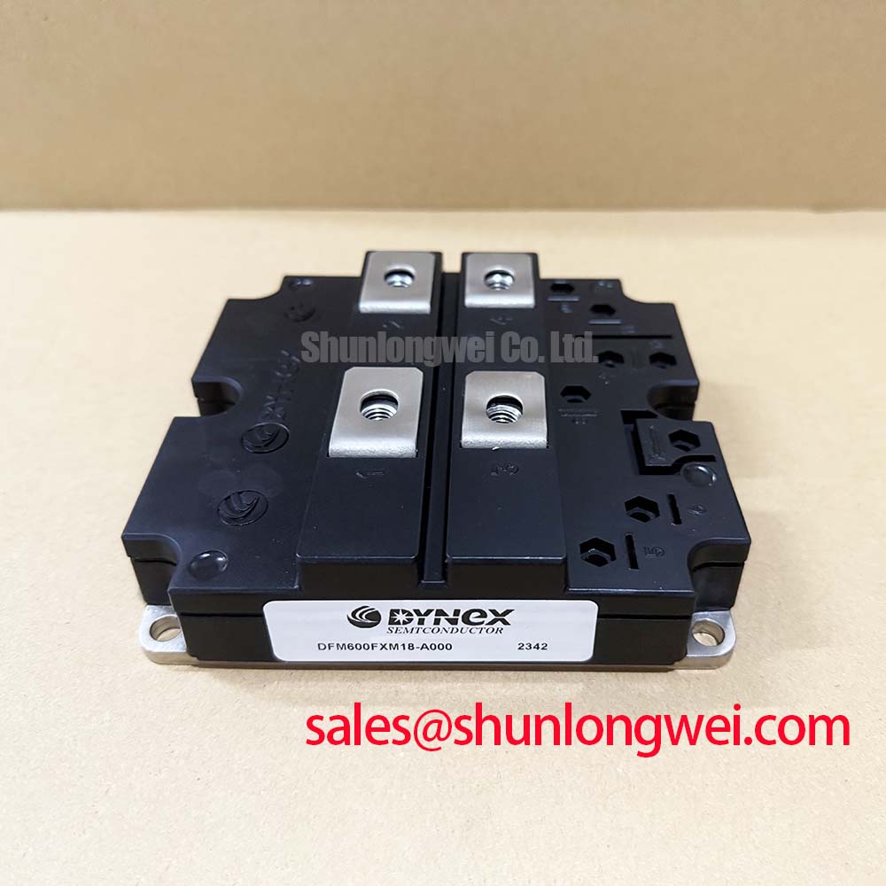
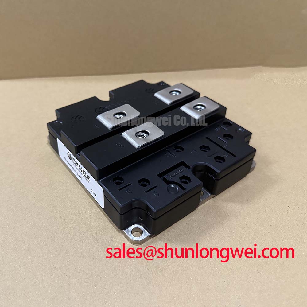
DFM600FXM18-A000 Dynex Fast Switching Dual IGBT Module
Introduction to High-Voltage Switching Efficiency
The DFM600FXM18-A000 is a high-performance Fast Switching Dual IGBT Module engineered by Dynex Semiconductor to bridge the gap between standard 1700V and ultra-high-voltage power systems. By offering an 1800V collector-emitter voltage rating, this module provides engineers with critical design headroom for applications utilizing 1200V DC links or 1500V photovoltaic architectures. It utilizes advanced trench gate technology to achieve a balance between conduction and switching losses, making it a robust choice for converters requiring elevated power densities.
- Core Specifications: 1800V | 600A | $V_{CE(sat)}$ 2.4V (typical at 125°C)
- Key Advantage: The 100V incremental safety margin over standard 1700V modules significantly reduces the risk of cosmic ray-induced failure and transient overvoltage damage.
- Engineering Value: Integrated fast-recovery diodes with soft recovery characteristics minimize EMI and peak voltage stress during high-frequency commutation.
For technical personnel evaluating dynamic performance and safe operating areas, the manufacturer provides detailed switching energy curves and thermal impedance data. Download the official DFM600FXM18-A000 datasheet (PDF).
UVP Technical Analysis: Headroom and Ruggedness
In high-power electronics, stray inductance is an ever-present challenge that results in voltage overshoots ($V = L cdot di/dt$) during turn-off. The DFM600FXM18-A000 addresses this through its 1800V rating. This extra 100V of blocking capability, compared to industry-standard 1700V parts, serves as a buffer that allows for higher switching speeds or less complex active clamping circuitry. This is particularly valuable in heavy-duty industrial environments where grid instability can cause unexpected DC link fluctuations.
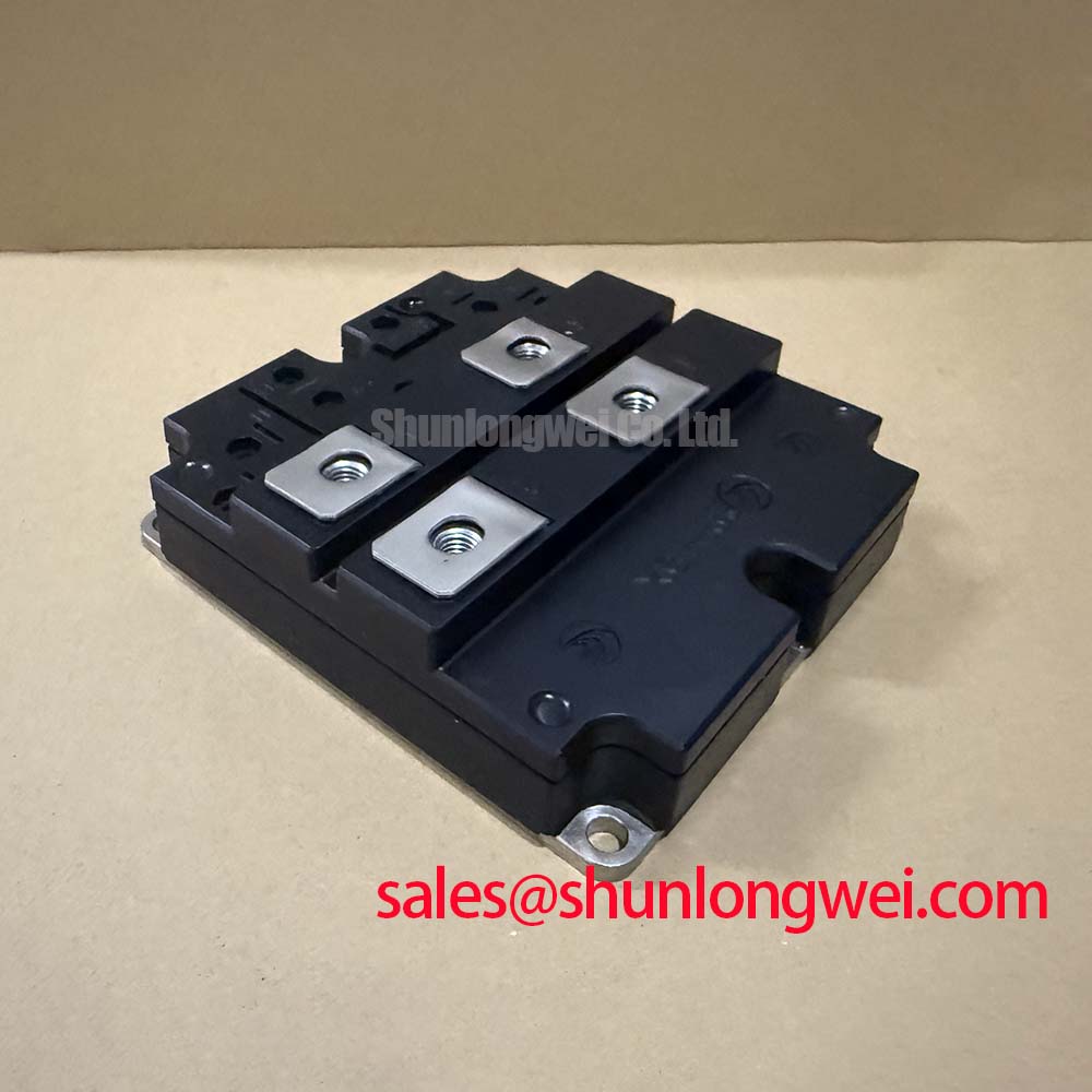
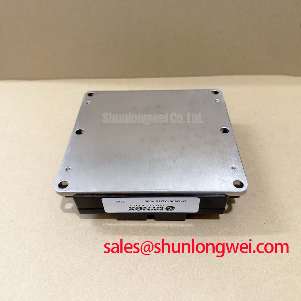
The module’s thermal management is defined by its isolated copper baseplate, which utilizes high-conductivity materials to reduce the junction-to-case thermal resistance ($R_{th(j-c)}$). To understand this parameter, one can visualize thermal resistance as the diameter of a drainage pipe; a wider pipe (lower resistance) allows heat to flow away from the silicon die more rapidly, preventing the “clogging” effect that leads to thermal runaway. With a typical $R_{th(j-c)}$ of 0.035°C/W for the IGBT section, the DFM600FXM18-A000 maintains cooler operation under continuous 600A loads, effectively extending the module’s power cycling lifetime.
Optimized Application Scenarios
The technical characteristics of the DFM600FXM18-A000 make it highly effective in the following fields:
- Renewable Energy Inverters: Ideal for 1500V solar central inverters where high efficiency and voltage blocking are required to reduce balance-of-system costs.
- Motor Drives and Traction: The 10µs short-circuit withstand time ($T_{sc}$) provides the necessary window for intelligent IGBT drivers to detect a fault and safely shut down the system without module destruction.
- High-Power UPS: Fast switching capabilities enable higher carrier frequencies, which reduces the size of output filters and improves the quality of the AC waveform.
- Welding Power Supplies: High ruggedness under cyclic loading ensures reliability in harsh industrial welding applications characterized by frequent load shifts.
Conclusion: The DFM600FXM18-A000 is best matched for high-reliability systems where a 1800V rating eliminates the need for multi-level topologies in 1200V DC links.
Key Specifications and Ratings
| Parameter Category | Specification | Value (Typical/Max) |
|---|---|---|
| Absolute Maximum Ratings | Collector-Emitter Voltage ($V_{CES}$) | 1800 V |
| Continuous Collector Current ($I_C$) | 600 A (at $T_C$ = 80°C) | |
| Peak Collector Current ($I_{CRM}$) | 1200 A | |
| Electrical Characteristics | Saturation Voltage ($V_{CE(sat)}$) | 2.4 V (at 600A, 125°C) |
| Gate Threshold Voltage ($V_{GE(th)}$) | 5.5 V to 7.5 V | |
| Short Circuit Withstand Time ($T_{sc}$) | 10 µs | |
| Thermal Properties | Junction-to-Case Resistance ($R_{th(j-c)}$) | 0.035 °C/W (IGBT) |
Engineer’s FAQ
Q: Why choose an 1800V module instead of a standard 1700V one?
A: The additional 100V blocking capability provides essential safety margins for systems operating at high DC link voltages, specifically accommodating surges and reducing sensitivity to terrestrial cosmic rays, which can cause early device failures.
Q: What is the recommended mounting torque for the power terminals?
A: According to mechanical specifications, terminal mounting should typically be maintained between 4.0 Nm and 6.0 Nm to ensure low contact resistance and prevent physical damage to the module housing.
Q: How does the trench gate structure affect high-frequency switching energy ($E_{sw}$)?
A: The trench gate structure reduces the stored charge and simplifies the gate-charge profile ($Q_G$), leading to lower turn-off losses compared to older planar designs, thereby enabling operation at higher carrier frequencies without exceeding thermal limits.
The DFM600FXM18-A000 serves as a high-capacity switching building block for modern energy infrastructures. By providing superior voltage blocking and optimized thermal paths, it enables power engineers to develop more resilient converters with reduced cooling overhead and simplified protection logic.