Infineon FS400R07A1E3: A High-Density 650V/400A IGBT Solution for EV Inverters
Infineon FS400R07A1E3 650V 400A HybridPACK 1 Sixpack IGBT
High-Density 650V/400A Solution for Hybrid and Electric Vehicle Inverters
The Infineon FS400R07A1E3 is a high-performance Sixpack IGBT module belonging to the renowned HybridPACK™ 1 family, specifically optimized for the main inverter systems of hybrid and electric vehicles (HEV/EV). By leveraging TRENCHSTOP™ IGBT3 technology paired with Emitter Controlled 3 (EmCon3) diodes, this module achieves an exceptional balance between conduction efficiency and switching speed. Engineers can expect a robust design capable of operating at elevated junction temperatures while maintaining high power density in a compact footprint.
- Core Specifications: 650V | 400A | $V_{CE(sat)}$ 1.45V (Typical)
- Key Advantages: Minimized parasitic inductance for reduced voltage overshoots and enhanced IGBT insulation reliability.
- Design Efficiency: Optimized thermal resistance between the chip and baseplate to lower cooling requirements in dense automotive environments.
Download Official FS400R07A1E3 Datasheet (PDF)
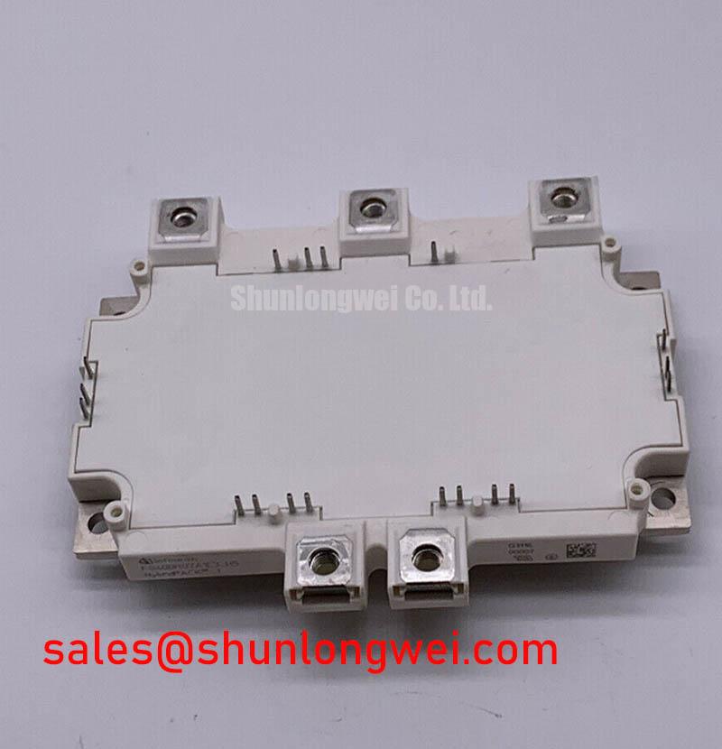

Technical Analysis of Trench/Fieldstop Technology
The FS400R07A1E3 utilizes the Infineon TRENCHSTOP™ IGBT3 architecture, which drastically reduces collector-emitter saturation voltage ($V_{CE(sat)}$). For the system designer, this translates to lower conduction losses during the “on” state. The integration of the Fieldstop layer allows for a thinner wafer, resulting in significantly lower gate charge requirements and improved switching characteristics compared to previous generations.
A critical parameter in this module is the thermal resistance ($R_{thJC}$), which describes the efficiency of heat transfer from the silicon junction to the case. To understand its importance, consider the analogy of a highway for heat: if $R_{thJC}$ is wide and clear (low resistance), thermal energy flows away from the chip rapidly, preventing overheating. Conversely, a narrow or congested highway (high resistance) forces the temperature to spike, risking premature device failure. The FS400R07A1E3 is designed with a low-resistance thermal path, ensuring stable operation even under continuous heavy loads.
Furthermore, the module addresses the impact of parasitic inductance through internal busbar optimization. This is particularly vital in high-current HEV applications where rapid di/dt transitions can lead to destructive voltage spikes. The HybridPACK™ 1 housing is specifically engineered to minimize these internal loops, simplifying the design of the external DC-link and snubber circuits.

Optimized Application Scenarios
- HEV/EV Main Inverters: The 400A current rating is best matched with medium-power drive motors, providing efficient DC-to-AC conversion with minimal thermal overhead.
- High-Power DC/DC Converters: Its 650V rating and Sixpack configuration allow for versatile implementation in multi-phase buck or boost topologies used for battery management.
- Industrial Motor Drives: While automotive-focused, the module’s high reliability makes it suitable for compact industrial Variable Frequency Drives (VFD) requiring rigorous power cycling.
Best Match Conclusion: The FS400R07A1E3 is most effective in space-constrained automotive inverters where Press-Fit assembly and high power density are the primary system design drivers.
Critical Specification Table
| Parameter Category | Specific Metric | Typical Value |
|---|---|---|
| Absolute Maximum Ratings | Collector-Emitter Voltage ($V_{CES}$) | 650 V |
| Continuous DC Collector Current ($I_{C}$) | 400 A (at $T_C = 25^circ C$) | |
| Electrical Characteristics | $V_{CE(sat)}$ ($I_{C}=400A, T_{vj}=125^circ C$) | 1.70 V |
| Gate Threshold Voltage ($V_{GE(th)}$) | 5.0 V to 6.5 V | |
| Thermal & Mechanical | Max Operating Junction Temperature | 150 °C |
| Internal Parasitic Inductance ($L_{sCE}$) | < 20 nH |
Engineer FAQ
Q1: What are the benefits of the Press-Fit pin technology in the FS400R07A1E3?
A1: Press-Fit technology provides a cold-welded, solder-free connection to the PCB. This significantly enhances vibration resistance and eliminates thermal stress issues associated with traditional soldering, making it ideal for the harsh mechanical environments of automotive drives.
Q2: How does the junction temperature affect the $V_{CE(sat)}$ of this module?
A2: The module exhibits a positive temperature coefficient for $V_{CE(sat)}$. As the junction temperature rises, the saturation voltage increases. This characteristic is beneficial for IGBT paralleling, as it encourages natural current sharing between chips and prevents thermal runaway.
Q3: What precautions should be taken to avoid common failure modes?
A3: To prevent issues described in root cause analysis of IGBT failures, ensure that the gate drive circuit provides sufficient negative bias during the off-state to prevent parasitic turn-on. Additionally, high-quality thermal interface material (TIM) must be applied uniformly to the baseplate to maintain the specified $R_{thCH}$.
The Infineon FS400R07A1E3 stands as a foundational component for engineers seeking to maximize the efficiency and longevity of electric drivetrain power stages. By integrating low-loss Trenchstop silicon with the mechanical resilience of the Press-Fit HybridPACK™ 1 housing, this module provides the technical certainty required for modern automotive power electronics.