Transient Analysis in Motion: The Physics of Securing Precision Electronics for Field Testing
Transient Analysis in Motion: The Physics of Securing Precision Electronics for Field Testing
In the controlled environment of a laboratory, the variables of electronic testing are predictable. An IGBT module sits securely on a heat sink, bolted to a vibration-free bench, while a high-resolution LCD display is mounted on an articulate arm. However, the reality of industrial engineering often demands that we leave the lab. Whether it is validating the regenerative braking efficiency of an Electric Vehicle (EV) on a test track or monitoring the logic control of a CNC arm on a factory floor, the “bench” becomes mobile, dynamic, and hostile.
At Shunlongwei Co. Ltd, we specialize in supplying the core components—from high-power semiconductors to industrial visualization modules—that drive these systems. Yet, we frequently encounter a critical logistical challenge: How do you temporarily yet securely mount sensitive electronic instrumentation in dynamic environments without damaging the substrate?
This article bridges the gap between electronic precision and mechanical engineering, exploring the physics of vacuum interface mechanics as a critical enabler for mobile electronic testing.
The Intersection of Electronics and Inertia
Consider the testing parameters of a standard industrial power module, such as the IGBT Modules we distribute from Infineon or Mitsubishi. When conducting a “Road Load Data Acquisition” (RLDA) test, engineers must monitor junction temperatures ($T_j$) and transient thermal impedance ($Z_{th}$) in real-time. This methodology, often discussed in IEEE power electronics literature, requires mounting data loggers, oscilloscopes, and Human-Machine Interfaces (HMIs) directly inside the vehicle cabin.
The challenge is twofold:
- Vibration Frequency: Industrial electronics are rated for specific vibration curves. Hard-mounting them to a chassis transfers high-frequency noise directly to the PCB, potentially causing solder fatigue or false sensor readings, a phenomenon detailed in Analog Devices’ vibration monitoring guides.
- Non-Destructive Rigging: Prototype vehicles and leased industrial machinery cannot be drilled into. The mounting solution must be temporary but possess a safety factor (SF) high enough to withstand G-forces during braking or cornering.
This is where advanced vacuum technology transcends simple “suction cups” and becomes a legitimate engineering solution.
Vacuum Physics: The Mathematics of the Hold
To secure a 2kg industrial LCD Display Panel to a glass windshield or a smooth composite panel, we rely on atmospheric pressure. The fundamental holding force ($F$) is derived from the pressure differential:
Where $P_{atm}$ is atmospheric pressure (approx. 14.7 PSI at sea level), $P_{vac}$ is the vacuum pressure achieved inside the cup, and $A$ is the effective surface area. As noted in NASA’s vacuum handling studies, even minor fluctuations in seal integrity can lead to catastrophic failure in vacuum-based holding systems. However, for electronics engineers, the most critical variable is often overlooked: Material Stability under Thermal Stress.
The Thermal Expansion Problem in EV Testing
In automotive testing, cabin temperatures can fluctuate wildly. A vehicle parked in the sun can reach dashboard temperatures exceeding 70°C, while air conditioning can rapidly cool it to 20°C. This thermal cycling is the enemy of standard PVC suction mounts.
We must consider the Coefficient of Linear Thermal Expansion ($\alpha$).
- Standard Plastics: $\alpha \approx 70-100 \times 10^{-6} m/m K$
- Aluminum Alloy: $\alpha \approx 23 \times 10^{-6} m/m K$
When a plastic pump housing expands four times faster than the metal spring or rubber plunger inside it, micro-gaps form, leading to vacuum loss. For expensive electronic logging gear, we strongly recommend using rigging systems based on Aviation Aluminum Pumps. These systems maintain airtight tolerances (often within 0.015mm) across a temperature range of -30°C to 120°C, ensuring that your $5,000 thermal camera doesn’t fall off the windshield during a heat soak test.
For heavy-duty setups involving multiple monitors or heavy sensor arrays, utilizing a specialized Vacuum Suction Cup with Metal Pump is not just a convenience; it is a risk mitigation strategy for your instrumentation.
Combating Shear Force: Friction Coefficients in Vertical Mounting
Electronics are rarely mounted on flat, horizontal tables in the field. They are mounted vertically—on windows, safety guards, or equipment racks. Here, gravity acts perpendicular to the vacuum force, introducing Shear Force.
The resistance to sliding is governed by the Coefficient of Static Friction ($\mu_s$). In cheap mounting solutions, the rubber pad is microscopically rough. Under load, these peaks and valleys shift, causing “creep”—where the device slowly slides down the glass over hours.
High-end rigging solutions employ a Mirror-Polishing Process on the rubber interface. This nanotechnology approach maximizes the molecular contact area between the rubber and the mounting surface. By increasing $\mu_s$, engineers can mount heavy Car Camera Mount Series systems or heavy data loggers vertically with near-zero creep, ensuring that the viewing angle of the HMI remains constant throughout the test duration.
Vibration Damping: Protecting the PCB
One often unintended benefit of using high-quality rubber vacuum mounts is vibration isolation. Rigidly bolting a PCB enclosure to a vibrating machine frame (hard mounting) transfers high-frequency energy directly to the solder joints. This can lead to intermittent connection failures or the cracking of ceramic capacitors.
The rubber interface of a professional suction cup acts as a high-frequency damper. The polymer chains in the rubber absorb and dissipate kinetic energy as heat (hysteresis). When setting up a test rig for sensitive components found in our Electronic Components Catalog, using a vacuum mount can effectively decouple the instrumentation from the high-frequency noise of the chassis, resulting in cleaner signal data and safer equipment.
Custom Solutions for Specialized PCBs
Not all electronics come in standard VESA-compatible cases. Often, R&D engineers are testing “breadboard” style prototypes or custom 3D-printed enclosures. In these scenarios, standard consumer mounts fail to provide necessary attachment points.
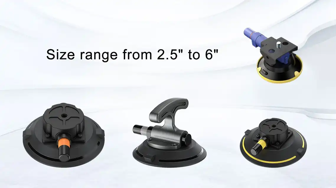
This creates a need for modularity. By sourcing individual industrial vacuum components, engineers can build custom rigs. For instance, integrating a customizable OEM Vacuum Suction Cup allows for the creation of bespoke mounting plates that align perfectly with the mounting holes of a specific driver board or heat sink assembly.
Conclusion
The reliability of a field test is defined by the weakest link in the chain. It serves no purpose to use a high-precision NEC LCD panel or a top-tier Infineon IGBT module if the physical mounting system fails mid-test due to thermal expansion or vibration.
By understanding the physics of the interface—specifically thermal coefficients, friction dynamics, and vacuum differential—electronics professionals can ensure that their data acquisition is as robust as the components they are testing. Treat your mounting hardware with the same engineering rigor as your electronic hardware, and the results will speak for themselves.
Explore our full range of industrial electronics at Shunlongwei.com.