Fuji Electric 7MBR15VKC120-50: 1200V 15A V-Series IGBT PIM Module Technical Overview and Applications
7MBR15VKC120-50 Fuji Electric 1200V 15A IGBT PIM Module
Introduction and Core Technical Highlights
The 7MBR15VKC120-50 is a high-performance Power Integrated Module (PIM) from Fuji Electric’s acclaimed V-Series. This “7-in-1” module is engineered to provide a complete power stage for small-scale industrial motor drives, consolidating a three-phase bridge rectifier, a three-phase inverter, and a dedicated brake chopper into a single compact housing. By integrating these functions, engineers can significantly reduce PCB real estate and simplify complex layout designs.
- Core Specifications: 1200V | 15A | VCE(sat) 2.10V (Typical)
- Key Advantages: Drastically reduced parasitic inductance via optimized internal busing and simplified assembly through a unified thermal interface.
- Engineering Intent: This module addresses the common challenge of PIM vs. discrete IGBT selection by offering a pre-tested, thermally matched solution that eliminates the need for separate rectifier and chopper components.
Download Official 7MBR15VKC120-50 Datasheet (PDF)
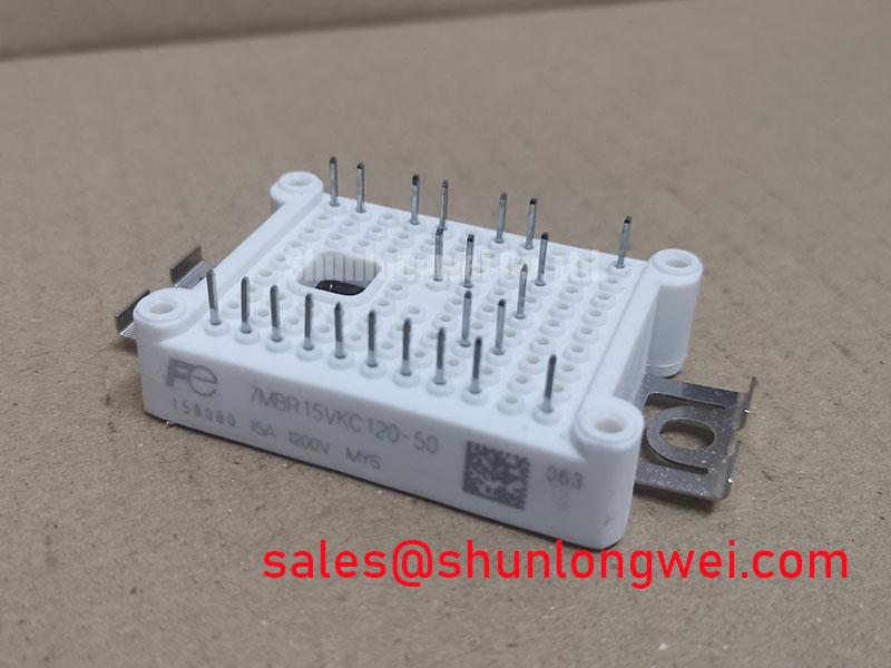
Technical Analysis of the V-Series Architecture
The 7MBR15VKC120-50 utilizes Fuji Electric’s Field Stop (FS) Trench technology, which is specifically optimized to balance switching speed and conduction losses. The typical collector-emitter saturation voltage (VCE(sat)) of 2.10V at 15A ensures that the device maintains high efficiency during heavy load cycles. This is critical for industrial environments where energy efficiency and thermal management are paramount.
One of the standout features of the 7MBR15VKC120-50 is its integrated NTC thermistor. This allows for real-time monitoring of the baseplate temperature, enabling the gate driver to implement proactive thermal throttling before the junction temperature exceeds its 150°C limit. An integrated NTC is essential for ensuring long-term system reliability in enclosed control cabinets with limited airflow.
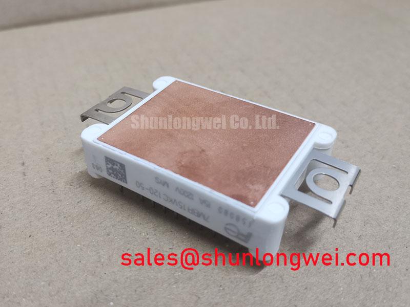
To better understand the thermal performance, one can use a fluid dynamics analogy: think of the module’s thermal resistance (Rth) as the diameter of a drainage pipe. A lower resistance value means heat can “flow” away from the silicon die much faster, preventing a “flood” of thermal energy that would otherwise cause device failure. With an Rth(j-c) of 1.05 K/W for the inverter IGBTs, the 7MBR15VKC120-50 excels at transferring waste energy to the heatsink efficiently.
Optimized Application Scenarios
This module is specifically tailored for applications requiring 1200V isolation and compact power delivery. Its integrated nature makes it ideal for:
- General Purpose Inverters: Ideal for variable frequency drives (VFDs) where space is at a premium and reliability is non-negotiable.
- Servo Control: The fast-switching characteristics of the V-Series IGBTs allow for precise motor positioning and response.
- Small Industrial Pumps and Fans: Simplifies the BOM by replacing multiple discrete power semiconductors with a single module.
- Braking Systems: The integrated brake chopper handles regenerative energy during motor deceleration, protecting the DC bus.
Best Match Conclusion: The 7MBR15VKC120-50 is the optimal choice for engineers designing 5.5kW to 7.5kW industrial drives requiring integrated temperature sensing and braking.
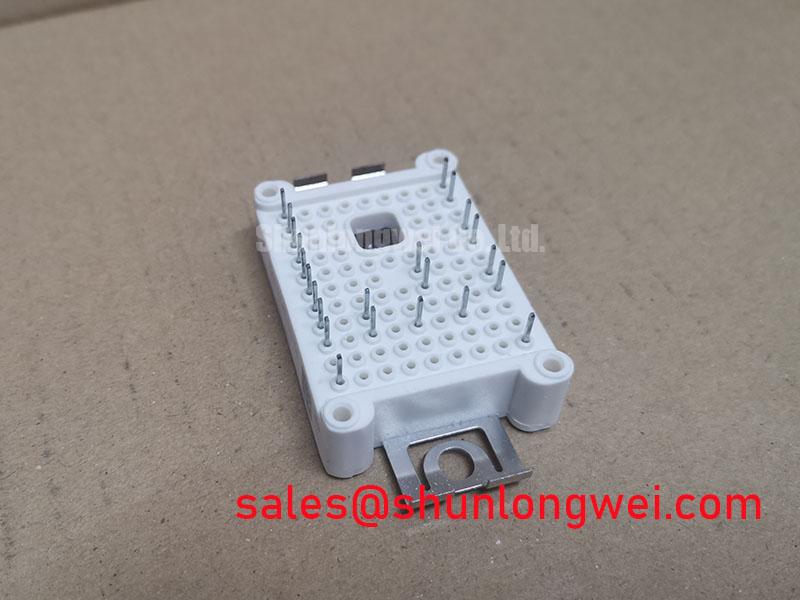
Key Specifications Table
| Category | Parameter | Value |
|---|---|---|
| Absolute Maximum Ratings | Collector-Emitter Voltage (VCES) | 1200V |
| Collector Current (IC) | 15A (Continuous) | |
| Junction Temperature (Tj) | -40°C to +150°C | |
| Electrical Characteristics | VCE(sat) (at IC=15A, Tj=25°C) | 2.10V (Typical) |
| Gate-Emitter Threshold (VGE(th)) | 5.5V to 8.5V | |
| Thermal Characteristics | Thermal Resistance (IGBT) | 1.05 K/W (Max) |
| Thermal Resistance (Diode) | 1.65 K/W (Max) |
Engineer’s FAQ
Q1: What is the benefit of the “7-in-1” PIM configuration for the 7MBR15VKC120-50?
A: It integrates the input rectifier bridge, the inverter bridge, and the brake chopper into one module. This reduces the number of components on your BOM, simplifies thermal management to a single heatsink, and minimizes parasitic inductance between power stages.
Q2: How should I handle the NTC thermistor output for system protection?
A: The NTC resistance values are provided in the datasheet (e.g., 5kΩ at 25°C). It should be connected to a controller’s ADC input via a voltage divider to monitor the module’s operating temperature and trigger a safe shutdown if limits are exceeded.
Q3: What is the recommended mounting torque for the baseplate?
A: According to the mechanical specifications, the M5 mounting screws should be tightened to a range of 2.5 to 3.5 N·m to ensure proper thermal contact without deforming the internal ceramic substrate.
The 7MBR15VKC120-50 provides a highly integrated, reliable foundation for modern industrial power electronics. By combining Fuji Electric’s V-Series efficiency with a comprehensive PIM architecture, it empowers engineers to build more compact and robust drive systems with simplified thermal and mechanical designs.