Infineon FZ1800R16KF4_S1: A High-Performance 1600V/1800A IGBT Module for Megawatt Applications
FZ1800R16KF4_S1 | 1600V 1800A Single IGBT Module – Infineon IHM
Introduction to the FZ1800R16KF4_S1 Power Stage
The FZ1800R16KF4_S1 is an ultra-high-power single IGBT module built on Infineon’s established IHM-B platform, designed specifically for megawatt-class industrial energy conversion. By integrating a 1.6kV collector-emitter blocking voltage with an immense 1800A nominal current rating, this module provides the robust power density required for heavy-duty applications. Its Unique Value Proposition (UVP) lies in the synergy between its high current handling capability and optimized thermal management architecture, ensuring operational stability under the severe power cycling demands of traction and central inverter systems.
- Core Specifications: 1600V | 1800A | $V_{CE(sat)}$ 2.30V (typical)
- Engineering Advantages: Enhanced power cycling reliability and high-speed switching capabilities with low tail current.
- User Intent Answer: For engineers asking about high-capacity power density, the FZ1800R16KF4_S1 addresses the need for fewer paralleled components in central solar inverters, reducing system complexity and parasitic inductance.
Download Official FZ1800R16KF4_S1 Datasheet (PDF)
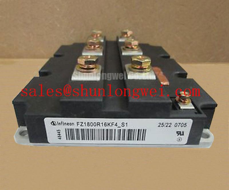
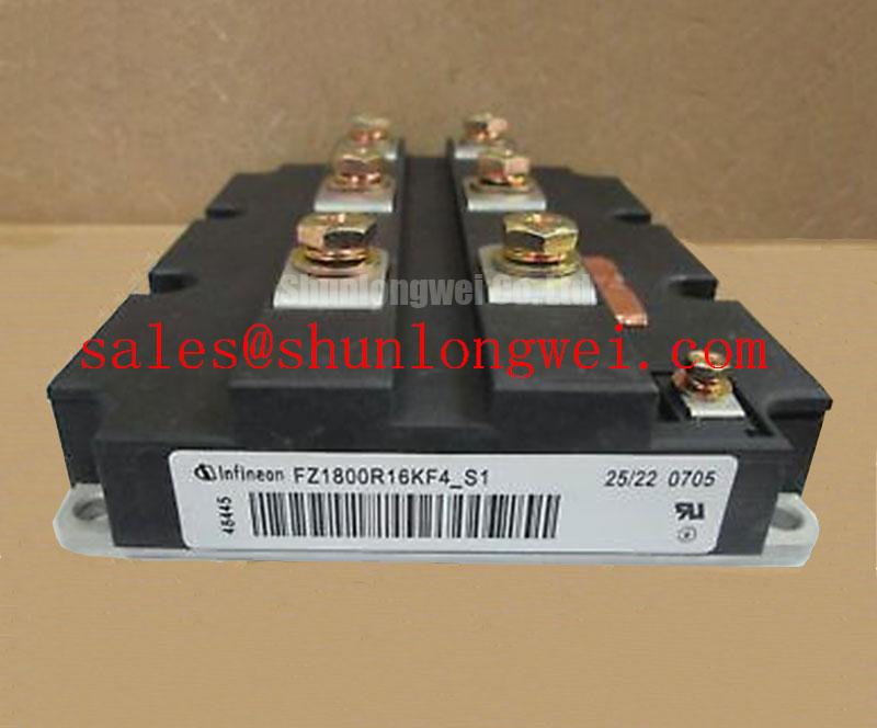
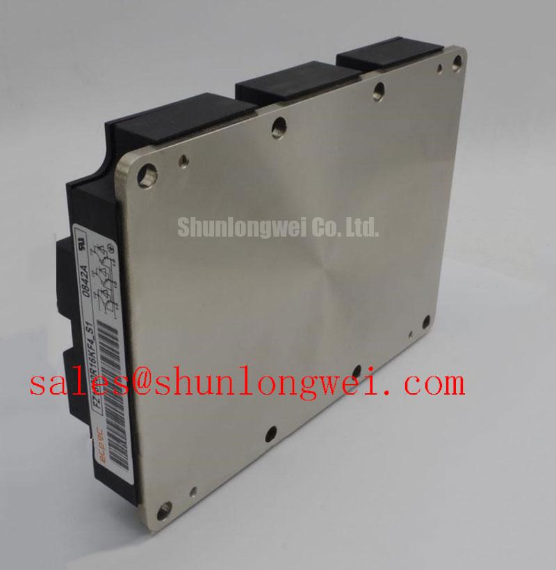
Technical Analysis of UVP and Engineering Significance
The engineering excellence of the FZ1800R16KF4_S1 is rooted in its Trench/Fieldstop technology. This architecture significantly lowers the $V_{CE(sat)}$ compared to previous generations, which directly translates to reduced conduction losses. In high-current environments reaching 1800A, even a millivolt reduction in saturation voltage prevents kilowatts of wasted energy from becoming heat. This efficiency is critical for maintaining long-term reliability in power semiconductors utilized in 24/7 industrial operations.
A vital parameter to consider is the module’s transient thermal impedance ($Z_{thJC}$). You can visualize thermal impedance as the width of a high-speed drain pipe; a lower value means heat can “drain” away from the silicon junctions much faster, preventing the “clogging” effect of localized hotspots. In the FZ1800R16KF4_S1, the AlSiC baseplate option and optimized internal bonding mitigate thermomechanical stress, which is often the primary cause of IGBT failures. By ensuring rapid heat dissipation, the module stays well within its safe operating area (SOA) even during peak load transients.
Furthermore, the design minimizes stray inductance within the package. In megawatt-class switching, high $di/dt$ rates can generate massive voltage spikes ($V = L cdot di/dt$). The IHM-B package used by the FZ1800R16KF4_S1 is engineered to keep internal inductance as low as possible. This simplifies the design of the external busbar and snubber circuits, protecting the collector-emitter junction from overvoltage breakdown during fast turn-off events. Engineers should evaluate the impact of parasitic inductance carefully when integrating these modules into high-frequency conversion stages.
Optimized Application Scenarios
- Railway Traction Drives: The module’s high power cycling capability and shock/vibration resistance make it ideal for the demanding duty cycles of locomotive propulsion.
- Central Solar Inverters: High current density allows for compact central inverter designs, utilizing the 1600V rating to handle the DC bus voltages typical of large-scale PV plants.
- Heavy Industrial Motor Control: Perfect for rolling mills and mining excavators where high-torque startup currents require robust $I_C$ headroom.
- Wind Energy Converters: The 1.8kA rating enables efficient power capture in offshore wind turbines, where minimizing component count is essential for maintenance reduction.
Best Matching Conclusion: The FZ1800R16KF4_S1 is the optimal choice for megawatt systems requiring high-reliability current switching with minimized conduction losses and superior thermal cycling endurance.
Key Specifications Table
| Parameter Group | Symbol | Value (Typical/Max) |
|---|---|---|
| Collector-Emitter Voltage | $V_{CES}$ | 1600 V |
| Continuous DC Collector Current | $I_{C,nom}$ | 1800 A (@$T_C=80^circ C$) |
| Collector-Emitter Saturation Voltage | $V_{CE(sat)}$ | 2.30 V (@$T_j=125^circ C$) |
| Total Power Dissipation | $P_{tot}$ | 14.5 kW (@$T_C=25^circ C$) |
| Gate-Emitter Threshold Voltage | $V_{GE(th)}$ | 4.5 V to 6.5 V |
| Thermal Resistance (per IGBT) | $R_{thJC}$ | 0.0086 K/W |
Engineer FAQ
Q1: What is the recommended mounting torque for the FZ1800R16KF4_S1 terminals?
A: Based on the IHM-B housing specifications, the mounting torque for the power terminals (M8/M4) and the mounting to the heat sink must be strictly adhered to—typically 8.0 to 10.0 Nm for power terminals—to ensure low contact resistance and prevent terminal fatigue.
Q2: How does the 1600V rating benefit a 1200V application?
A: The 1600V rating provides a significant safety margin against cosmic radiation-induced failures and transient voltage spikes, making the FZ1800R16KF4_S1 exceptionally robust for high-reliability systems operating at 1000V-1200V DC links.
Q3: What thermal interface material (TIM) is recommended for this module?
A: High-performance thermal grease or phase-change materials with high thermal conductivity are required. Given the module’s 14.5kW potential dissipation, ensuring proper thermal management and flat heat sink surfaces is critical to avoid junction overheating.
The FZ1800R16KF4_S1 stands as a cornerstone component for engineers designing high-power conversion stages. Its 1800A rating and optimized IHM architecture empower the creation of high-efficiency, durable megawatt converters while significantly simplifying the mechanical and electrical challenges of ultra-high current switching.