Technical Analysis of the Fuji 7MBR35U4P120 1200V 35A PIM IGBT Module
7MBR35U4P120 Fuji 1200V 35A PIM IGBT Module Analysis
The 7MBR35U4P120 is an integrated Converter-Inverter-Brake (CIB) power module developed for compact industrial power conversion. It integrates an input diode bridge rectifier, a six-switch three-phase inverter, a dynamic brake chopper, and an internal thermistor within a single compact package. As a specialized distributor of power semiconductors, we provide technical specifications to assist engineers in evaluating the performance metrics of the 7MBR35U4P120 for motion control designs.
- Core Ratings: 1200V VCES | 35A IC (Inverter Stage) | 1600V VRRM (Converter Stage)
- System Benefits: Minimized board footprint and reduced layout parasitics compared to discrete components.
- Design Solved: Eliminates the complex trace routing required when pairing separate rectifiers, inverters, and brake switches.
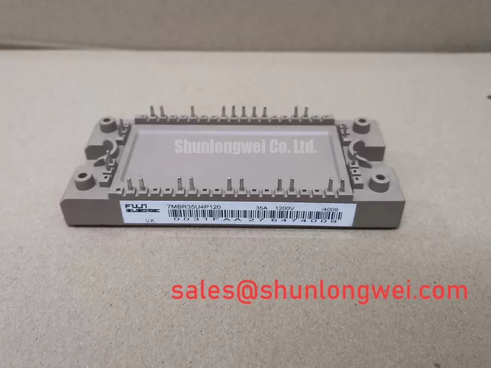


Technical Architecture and Performance Analysis
The internal inverter of the 7MBR35U4P120 utilizes trench-gate field-stop silicon technology, providing a low saturation voltage VCE(sat) alongside controlled switching losses. The integrated forward-recovery and free-wheeling diodes offer soft-recovery behavior, helping engineers control electromagnetic interference (EMI) during high-frequency pulse-width modulation (PWM).
You can conceptualize the module’s junction-to-case thermal resistance (Rth(j-c)) as a wide conduit: a lower thermal resistance allows switching-induced heat to move rapidly into the heatsink, keeping internal die temperatures well within safe operating boundaries. Managing dynamic heat dissipation is essential, and engineers frequently review transient thermal impedance curves to calculate pulse margins under cyclic loading.
Incorporating an integrated NTC inside the 7MBR35U4P120 enables direct baseplate temperature feedback. This allows controller logic to execute over-temperature trip protection without mounting external sensors. Compared to discrete layouts, evaluating a PIM vs discrete IGBT architecture demonstrates a substantial drop in internal stray loop inductance, curtailing dangerous turn-off overvoltage spikes.


Target Application Scenarios
- Variable Frequency Drives (VFDs): Serves 400V–480V three-phase industrial motor drives requiring an integrated rectifier, inverter, and dynamic braking switch in one unit.
- Servo Drive Systems: High dynamic response and integrated thermal sensing support precision robotics and CNC machinery.
- Industrial Pump and Fan Inverters: Low on-state conduction losses provide efficient power conversion under continuous duty cycles.
- Auxiliary Inverters and UPS: Delivers compact conversion stages for secondary power supplies and power conditioning equipment.
The 7MBR35U4P120 delivers an optimal balance of integrated stages and low conduction loss for 400V industrial AC drive architectures.
Key Electrical & Thermal Specifications
| Parameter | Symbol | Test Conditions / Subsystem | Typical / Max Value | Unit |
|---|---|---|---|---|
| Collector-Emitter Voltage | VCES | Inverter / Brake Stage, Tj = 25°C | 1200 | V |
| Continuous Collector Current | IC | Inverter Stage, TC = 80°C | 35 | A |
| Pulsed Collector Current | ICP | Inverter Stage, 1ms pulse | 70 | A |
| Repetitive Peak Reverse Voltage | VRRM | Converter Bridge Diode Stage | 1600 | V |
| Collector-Emitter Saturation Voltage | VCE(sat) | IC = 35A, VGE = 15V, Tj = 25°C | 2.10 (typ) / 2.45 (max) | V |
| Diode Forward Voltage | VF | IF = 35A, VGE = 0V, Tj = 25°C | 1.90 (typ) / 2.30 (max) | V |
| Thermal Resistance (IGBT) | Rth(j-c) | Per Inverter IGBT Switch | 0.65 (max) | °C/W |
| Isolation Voltage | Visol | AC 1 min, between terminals and baseplate | 2500 | V |
Engineering FAQ
What gate driver voltage levels are recommended for the 7MBR35U4P120?
A standard gate-emitter drive voltage of +15V is recommended for turn-on to ensure full saturation and minimum on-state losses. A negative gate bias between -5V and -15V during turn-off is advised to prevent dv/dt-induced parasitic turn-on.
How should thermal interface material (TIM) be applied during installation?
A uniform layer of thermal grease with a thickness of 60µm to 100µm should be applied across the copper baseplate. Ensure that mounting screws are torqued evenly according to manufacturer limits to avoid substrate deformation.
Can the internal brake chopper be operated independently?
Yes. The brake IGBT and diode terminals are isolated from the inverter control pins, allowing the external control circuit to trigger dynamic braking resistors only when DC-link voltage exceeds preset limits.
Procurement & Integration Support
The 7MBR35U4P120 provides hardware engineers with an integrated power stage that reduces board space and simplifies system assembly. As an independent distributor, we verify manufacturer specifications and support sourcing for current and legacy industrial automation platforms.