Semikron SKM400GB128D 1200V 400A IGBT Module: Technical Overview and Application Guide
Semikron SKM400GB128D IGBT Module Technical Overview
The Semikron SKM400GB128D is a 1200V, 400A half-bridge power semiconductor module housing Trench IGBT chips paired with soft-recovery CAL (Controlled Axial Lifetime) diodes. Built for demanding power switching topologies, the module combines a low saturation voltage with elevated short-circuit endurance, allowing power engineers to optimize inverter stages while preserving system ruggedness under load faults.


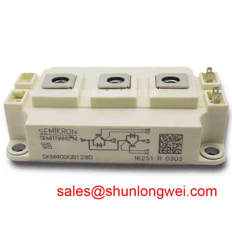
Key Highlights:
- Core Ratings: 1200 V collector-emitter voltage | 400 A continuous collector current (at Tc = 80°C) | VCE(sat) of 1.9 V typical.
- Thermal & Electrical Value: Low thermal impedance via direct copper bonded substrate simplifies thermal sinking requirements.
- Driver Pairing: Compatible with conventional 15V gate drivers utilizing standard desaturation detection networks.
Download Official Datasheet (PDF)
Technical Analysis Around the Unique Value Proposition
The SKM400GB128D centers its value proposition on balanced switching dynamics and thermal efficiency within the standard SEMITRANS 3 footprint. The module incorporates homogeneous trench gate silicon, providing a collector-emitter saturation voltage (VCE(sat)) of 1.9 V at rated current (25°C). This low on-state voltage drop minimizes conduction losses during continuous load intervals, preventing unnecessary heat buildup in industrial converter cabinets.
Thermal management is supported by a junction-to-case thermal resistance (Rth(j-c)) of 0.06 K/W per IGBT switch. To visualize this parameter, consider thermal resistance as the constriction in a drainage pipe. A lower numerical value represents a wider pipe diameter, allowing thermal energy generated at the silicon junction to drain rapidly into the cooling plate without backing up into excessive junction temperatures.
Complementing the IGBT switches, the antiparallel CAL diodes provide soft-recovery behavior. A common engineering problem in fast-switching bridges is transient overvoltage caused by diode reverse recovery currents interacting with parasitic bus inductance. The integrated soft-recovery diodes dampen voltage ringing (dv/dt), limiting electromagnetic interference (EMI) and lightening the burden on external snubber networks.
The module construction uses an isolated baseplate constructed via direct copper bonding (DCB) on ceramic, rated for an insulation test voltage of 2500 VRMS (1 minute). This construction maintains mechanical integrity across thermal cycling while ensuring safe clearance in high-voltage industrial enclosures.
Optimized Application Scenarios
- AC Motor Drives (VFDs): The 400A capacity and stable VCE(sat) temperature coefficient support three-phase inverter output stages in 200 kW to 250 kW drives.
- Uninterruptible Power Supplies (UPS): Fast switching characteristics and low commutation losses accommodate 10 kHz to 15 kHz pulse-width modulated online conversion.
- Welding Power Inverters: Robust short-circuit safe operating area (SCSOA) withstands repeated secondary-side short circuits and dynamic arc ignition surges.
- Photovoltaic Central Inverters: The 1200V blocking voltage allows safe operation on 800V DC intermediate buses with sufficient headroom for inductive line transients.
Optimal system deployment: Well matched for 400V–480V AC utility-fed inverters requiring 400A continuous phase legs with standard forced-air or liquid cooling plates.
Key Specifications Table
| Parameter | Symbol | Conditions | Rated Value |
|---|---|---|---|
| Absolute Maximum Ratings | |||
| Collector-Emitter Voltage | VCES | Tj = 25 °C | 1200 V |
| Continuous Collector Current | IC | Tc = 25 °C / Tc = 80 °C | 500 A / 400 A |
| Pulsed Collector Current | ICRM | tp = 1 ms | 800 A |
| Gate-Emitter Voltage | VGES | Continuous | ±20 V |
| Electrical Characteristics (per switch) | |||
| Collector-Emitter Saturation Voltage | VCE(sat) | IC = 400 A, VGE = 15 V, Tj = 25 °C | 1.9 V typ. (2.2 V max.) |
| Gate Threshold Voltage | VGE(th) | VCE = VGE, IC = 12 mA | 5.0 V – 6.5 V |
| Diode Forward Voltage | VF | IF = 400 A, VGE = 0 V, Tj = 25 °C | 1.8 V typ. (2.2 V max.) |
| Thermal and Mechanical Data | |||
| Thermal Resistance (IGBT) | Rth(j-c) | Per IGBT switch | 0.06 K/W |
| Thermal Resistance (Diode) | Rth(j-c)D | Per freewheeling diode | 0.12 K/W |
| Isolation Test Voltage | Visol | AC, 1 min, 50 Hz | 2500 V |
Engineering FAQ
What gate driver voltage and external gate resistance are recommended for the SKM400GB128D?
The module operates optimally with a nominal gate drive voltage of +15 V for full saturation and a negative bias between -5 V and -8 V to prevent parasitic dv/dt-induced turn-on. Datasheet reference testing uses external gate resistances around 1.5 Ω to 2.5 Ω; adjusting this resistance allows designers to balance switching loss against turn-off voltage spikes.
How should heatsink mounting and thermal interface material be handled?
Mounting surfaces require a flatness better than 50 µm and roughness under 6 µm. Apply thermal grease in a uniform 50 µm to 100 µm layer across the copper baseplate. Tighten baseplate mounting screws to 3.0–5.0 Nm and main terminal M6 connections to 2.5–5.0 Nm in sequential stages to avoid mechanical stress on the internal substrate.
What is the short-circuit withstand capability of this module?
The SKM400GB128D specifies a short-circuit withstand time (tpsc) of 10 µs at nominal bus voltages (VCC = 750 V) and gate-emitter bias of 15 V (starting Tj ≤ 125 °C). This gives standard desaturation detection circuits sufficient response time to shut down the gate driver without exceeding SOA boundaries.
How does the SKM400GB128D differ from related half-bridge models like the SKM400GB124D?
While both belong to the SEMITRANS 3 family, the SKM400GB128D integrates upgraded trench cell architectures and tailored CAL diodes optimized for lower on-state saturation and improved EMC behavior, detailed further in our review of the Semikron SKM400GB124D module.
Application and Integration Support
The SKM400GB128D provides system builders with a standardized half-bridge building block characterized by low conduction drop, robust 10 µs short-circuit capability, and thermally predictable DCB construction. For detailed bill-of-materials verification, engineering lot inquiries, and commercial procurement timelines, please contact our technical sales team.