Mitsubishi PM200RSD060 600V 200A Intelligent Power Module: Technical Overview and Engineering Guide
PM200RSD060 Mitsubishi Intelligent Power Module (IPM)
The PM200RSD060 is an isolated-base 3-phase inverter bridge IPM (Intelligent Power Module) rated at 600V and 200A. It integrates 3rd generation Planar IGBT dies, fast soft-recovery freewheeling diodes, and dedicated gate drive logic with multi-layer self-protection. This configuration eliminates external drive circuitry mismatches, optimizing high-power conversion stages in motor controllers and industrial inverters.
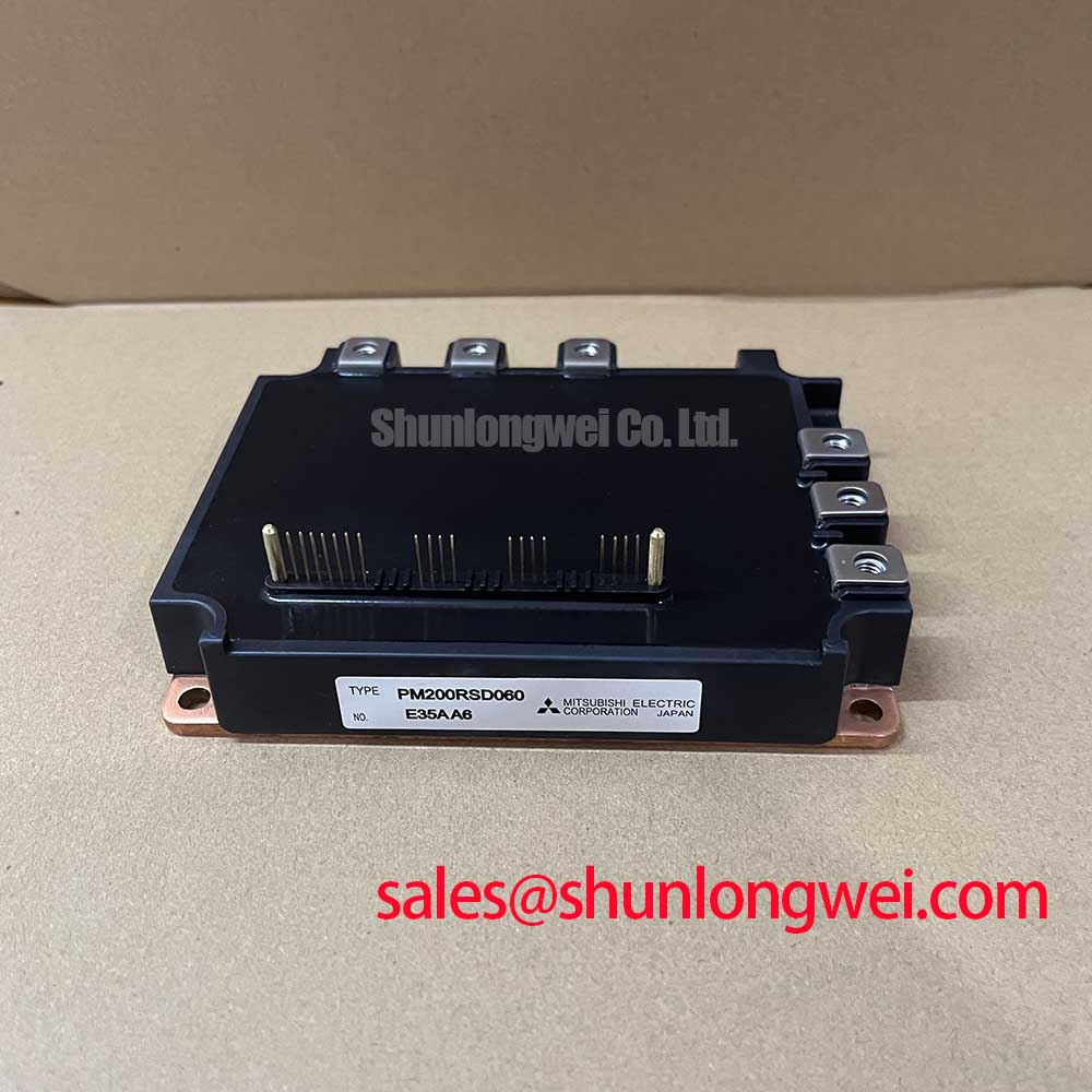
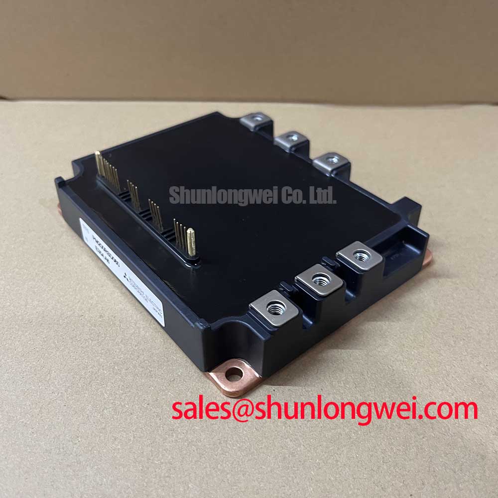
- Core Ratings: 600V collector-emitter voltage ($V_{CES}$), 200A continuous collector current ($I_C$), and $V_{CE(sat)}$ of 1.8V (typical at 200A, $T_j = 25^circtext{C}$).
- Integrated Driver & Logic: Dedicated on-chip gate drive tailored to internal planar IGBT switching dynamics, avoiding external gate resistor tuning.
- Comprehensive Fault Safeguards: Monolithic overcurrent, short-circuit, overtemperature, and control supply under-voltage lockout (UVLO) circuits with fault output signaling.
Engineering Dynamics & UVP: On-Chip Gate Driving and Silicon Protection
Operating high-current switches at 15 kHz to 20 kHz requires precise gate charge extraction to curb dynamic losses while managing EMI generation. The PM200RSD060 leverages an internal HVIC gate driver scheme. This setup matched impedance directly at the die interface, suppressing gate oscillation and transient $dV/dt$-induced parasitic turn-on without demanding external negative bias rails.

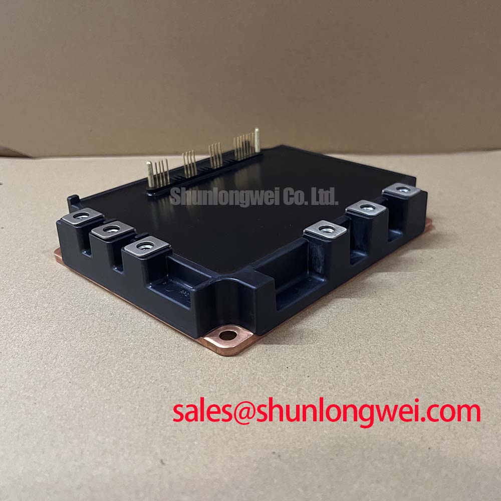
Thermal dissipation efficiency relies heavily on the module’s junction-to-case thermal resistance ($R_{th(j-c)}$). Think of thermal resistance like the width of a drainage channel: a lower thermal resistance ensures generated heat drains swiftly from the silicon junction to the heatsink. With an inverter IGBT $R_{th(j-c)}$ of only 0.22 °C/W, silicon junction temperatures remain controlled even under aggressive pulse-width modulation.
The integrated over-temperature detection mechanism samples junction status directly at the silicon substrate. By bypassing the thermal latency inherent in external baseplate thermistors, the PM200RSD060 triggers soft shutdown protocols before local chip temperatures reach destructive avalanche limits.
Target Application Scenarios
- Industrial Variable Frequency Drives (VFDs): Serves 15 kW to 22 kW AC motor control systems operating from 200V–240V mains, matching continuous 200A load demands.
- Servo Amplifiers & Motion Stages: Low internal parasitic layout enables clean current reproduction in fast cyclic positioning loops.
- Uninterruptible Power Supplies (UPS): Supports three-phase online inverter conversion stages where low conduction loss ($V_{CE(sat)} = 1.8text{V}$) maintains high total conversion efficiency.
- Switching Power Inverters & Welder Stages: High current tolerance and rugged diode recovery handle regenerative inductive flyback stresses.
Optimal Fit: 200V–240V AC line industrial drives requiring a 3-phase, 200A switching stage with self-contained protection networks.
Key Datasheet Specifications
| Parameter | Symbol | Condition / Description | Rated Value |
|---|---|---|---|
| Collector-Emitter Voltage | $V_{CES}$ | $V_D = 15text{V}, V_{CIN} = 15text{V}$ | 600 V |
| Continuous Collector Current | $I_C$ | $T_c = 25^circtext{C}$ | 200 A |
| Peak Collector Current | $I_{CP}$ | $T_c = 25^circtext{C}$, pulse width 1ms | 400 A |
| Collector Dissipation | $P_C$ | $T_c = 25^circtext{C}$, per 1 IGBT element | 568 W |
| Collector-Emitter Saturation Voltage | $V_{CE(sat)}$ | $V_D = 15text{V}, I_C = 200text{A}, T_j = 25^circtext{C}$ (Typical) | 1.8 V (Max 2.7 V) |
| FWDi Forward Voltage | $V_{EC}$ | $-I_C = 200text{A}, V_{CIN} = 15text{V}, T_j = 25^circtext{C}$ (Typical) | 2.0 V (Max 3.0 V) |
| Turn-On Switching Time | $t_{on}$ | $V_D = 15text{V}, V_{CC} = 300text{V}, I_C = 200text{A}, T_j = 125^circtext{C}$ | 0.5 µs (Typ 0.8 µs Max) |
| Turn-Off Switching Time | $t_{off}$ | $V_D = 15text{V}, V_{CC} = 300text{V}, I_C = 200text{A}, T_j = 125^circtext{C}$ | 2.2 µs (Typ 3.2 µs Max) |
| Thermal Resistance, IGBT | $R_{th(j-c)Q}$ | Junction to case, per element (Max) | 0.22 °C/W |
| Isolation Voltage | $V_{iso}$ | $60text{Hz}$, Sinusoidal, Charged part to Baseplate, AC 1 min | 2500 Vrms |
Engineering FAQ
Q: What isolated power supply topology is required to operate the PM200RSD060 control stage?
A: The PM200RSD060 requires four isolated +15V DC power supplies: three independent supplies for each high-side driver (U, V, W phases) and one shared supply for the common low-side drive and protection block.
Q: How does the internal short-circuit protection (SC) safeguard the module during a phase-to-phase short?
A: The module constantly monitors device current. If the current exceeds the internal short-circuit threshold ($I_{SC}$), the gate driver initiates a controlled soft turn-off to avoid high inductive voltage spikes ($L cdot di/dt$), simultaneously pulling the Fault output pin LOW.
Q: What are the recommended mounting guidelines to prevent mechanical stress on the DBC substrate?
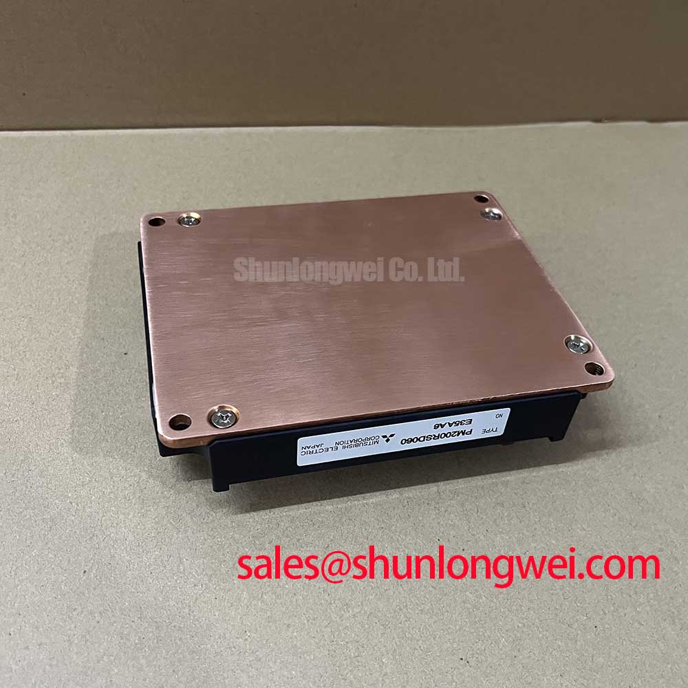
A: Heatsink flatness must be within 100 µm over the mounting footprint. Use a uniform 100–150 µm layer of high-performance thermal interface material, and torque mounting screws progressively in diagonal sequence to 2.5–3.5 N·m.
Q: What is the minimum recommended dead time for switching logic?
A: While internal gate drive timing is tightly managed, controller dead time ($t_{dead}$) must account for signal propagation and optocoupler delay variations. A dead time setting of $ge 2.0text{ µs}$ ensures shoot-through prevention across all operating temperature ranges.
The PM200RSD060 integrates three-phase switching and gate drive logic into a single mechanically robust footprint. By incorporating fast protection directly at the die level, it minimizes development cycles for heavy-duty motor drive platforms requiring dependable 600V/200A operation.