GD100HFL120C2S Half-Bridge IGBT Module: 1200V 100A Technical Breakdown
GD100HFL120C2S Half-Bridge IGBT Module: 1200V 100A Technical Breakdown
The StarPower GD100HFL120C2S is a 1200V, 100A half-bridge IGBT Module engineered for medium-to-high-power switching applications. Utilizing advanced Field-Stop Trench gate technology, the device delivers a balanced trade-off between low conduction loss and minimal turn-off dissipation. It integrates an ultra-fast soft-recovery freewheeling diode per switch to mitigate reverse-recovery transients and EMI in industrial power converters.
Key Ratings: 1200V Breakdown Voltage | 100A Continuous Collector Current (at TC = 80°C) | Typical VCE(sat) of 1.95V (at 25°C).
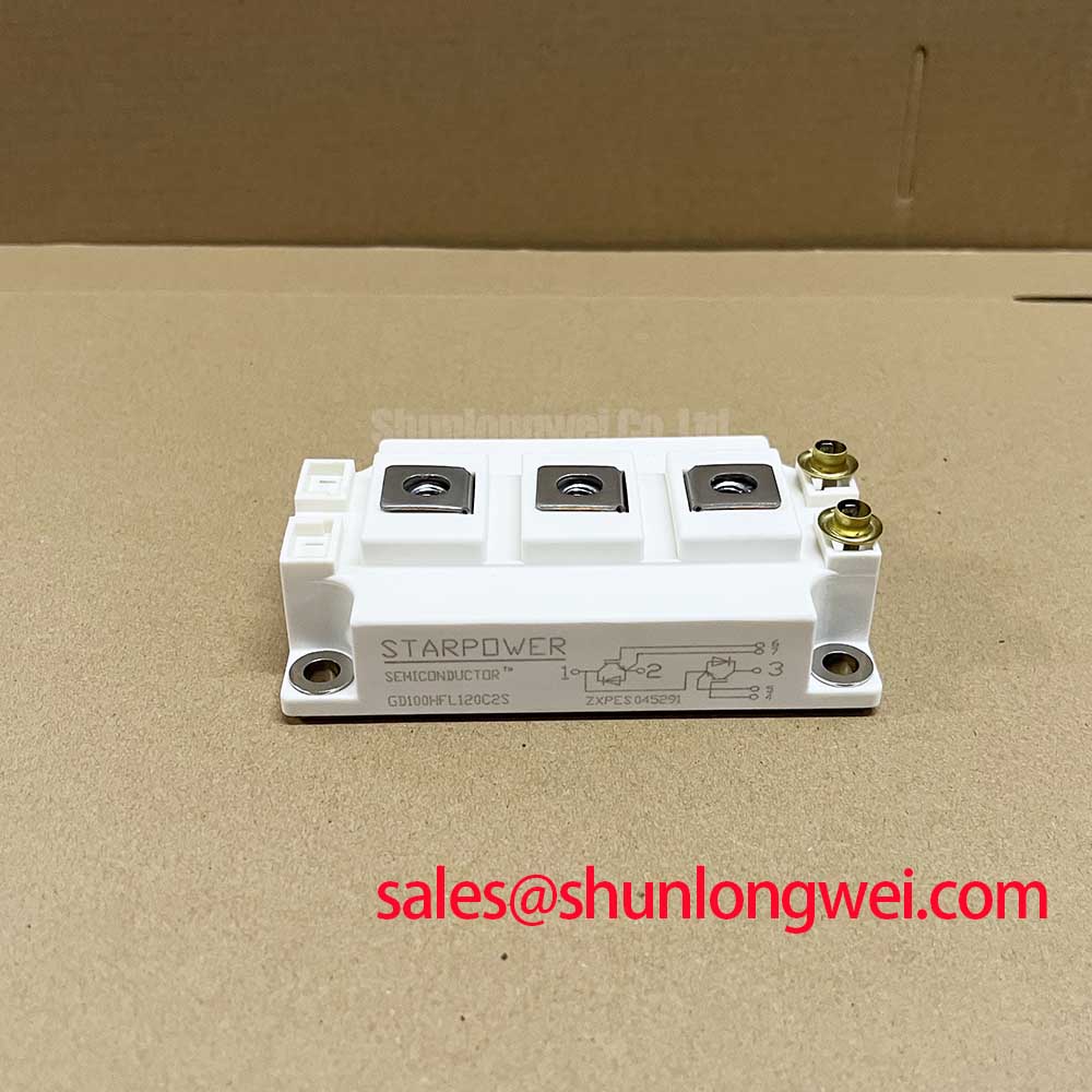
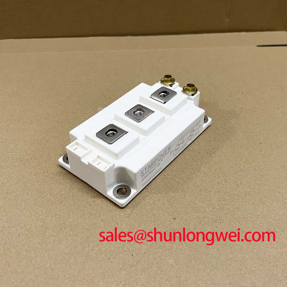
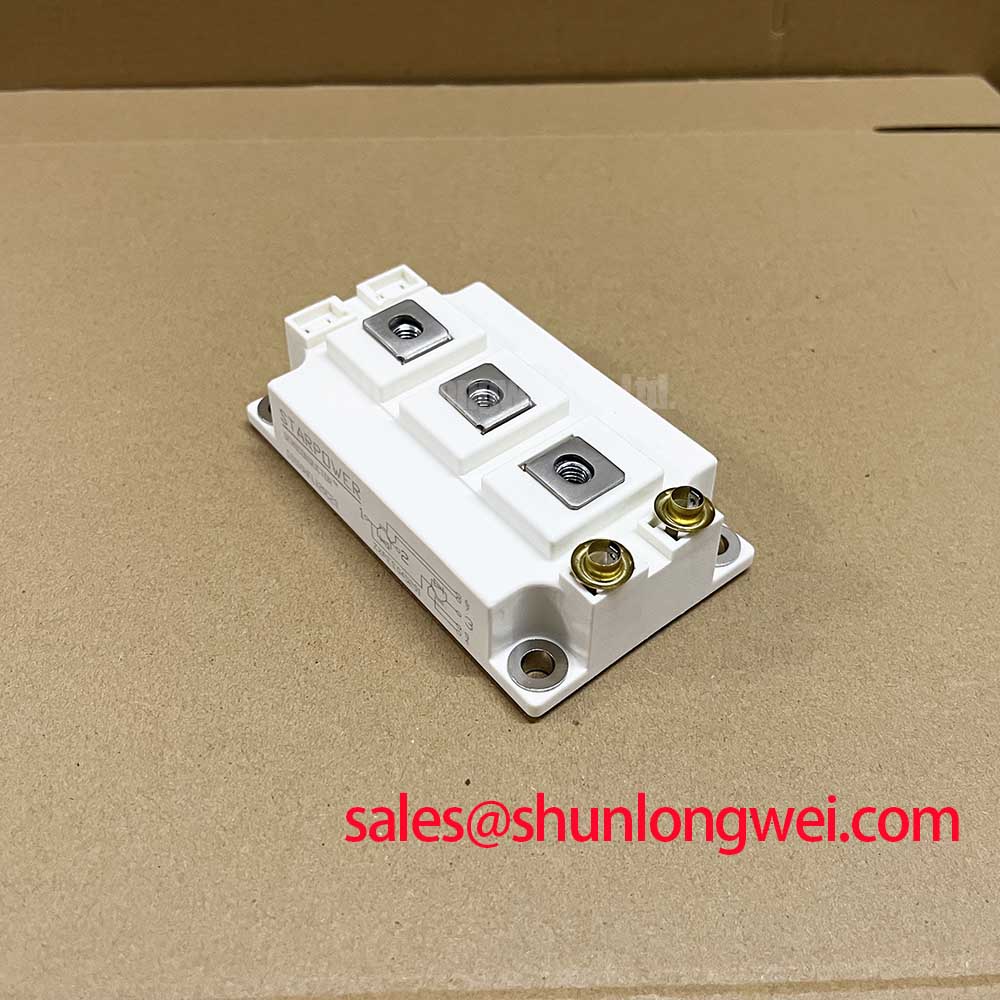
Technical Architecture and Conduction Efficiency
The GD100HFL120C2S leverages a field stop IGBT structure to decrease substrate thickness while maintaining breakdown voltage integrity. This thin-wafer design yields a low saturation voltage (VCE(sat)), directly curbing steady-state thermal generation during high continuous current operation. In addition, the positive temperature coefficient of VCE(sat) facilitates parallel operation by naturally sharing load current among multiple modules.
Thermal dissipation is governed by an isolated DBC (Direct Bonded Copper) substrate with an engineered copper baseplate. One can visualize thermal resistance like fluid friction inside a conduit: a lower thermal resistance (Rth(j-c)) functions like a wider, unconstricted pipe, allowing excessive junction heat to escape effortlessly into the heatsink. By maintaining junction-to-case thermal resistance at 0.24 K/W per IGBT, the GD100HFL120C2S operates reliably within high ambient thermal envelopes.
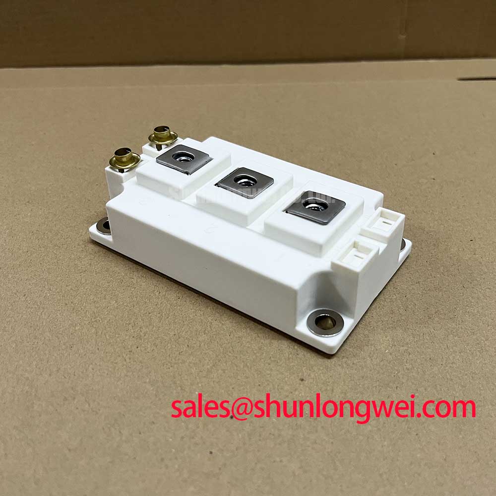


Complementing the IGBT chips, the anti-parallel diodes exhibit soft recovery characteristics. Understanding how the free-wheeling diode dictates system performance is essential; the reduced peak reverse recovery current (Irr) suppresses high dv/dt spikes, reducing turn-on losses in the complementary IGBT and reducing common-mode EMI filtering requirements on the PCB layout.
Target Application Scenarios
- Industrial Motor Inverters: The 10th-microsecond short-circuit withstand capability (tsc ≥ 10 µs at 150°C) provides sufficient protection margins for three-phase Variable Frequency Drive (VFD) designs.
- Uninterruptible Power Supplies (UPS): Low switching loss up to 20 kHz switching frequencies allows compact magnetic component selection in online double-conversion UPS topologies.
- Induction Heating & Welding: The half-bridge layout in standard C2S packaging simplifies low-inductance busbar connections for resonant inverters.
- Solar Inverters: High dielectric isolation rating (2500V AC RMS) meets safety standards for grid-tied transformerless solar converters.
Conclusion: The GD100HFL120C2S offers optimal efficiency for 380V-480V AC motor drives and 20kVA-40kVA industrial conversion systems.
Key Technical Specifications
| Parameter | Symbol | Rating / Condition | Unit |
|---|---|---|---|
| Collector-Emitter Voltage | VCES | 1200 (Tvj = 25°C) | V |
| Continuous DC Collector Current | IC | 100 (TC = 80°C) / 140 (TC = 25°C) | A |
| Collector-Emitter Saturation Voltage | VCE(sat) | 1.95 (Typ, IC=100A, VGE=15V, 25°C) | V |
| Gate-Emitter Threshold Voltage | VGE(th) | 5.0 to 6.8 (IC = 4.0mA) | V |
| Total Power Dissipation (per switch) | Ptot | 520 (TC = 25°C, Tvj = 150°C) | W |
| Thermal Resistance, Junction to Case | Rth(j-c) | 0.24 (IGBT) / 0.45 (Diode) | K/W |
| Isolation Test Voltage | VISOL | 2500 (AC, 1 min, 50Hz) | V |
Engineering FAQ
Q: What is the recommended gate resistor (Rg) value for driving the GD100HFL120C2S?
A: The datasheet references a nominal gate resistance of 5.1 Ω to 10 Ω for optimized switching speed and oscillation suppression. Tuning Rg allows engineers to manage turn-on di/dt and turn-off overshoot according to parasitic DC busbar inductance.
Q: How do engineers perform thermal calculations using the module impedance data?
A: System designers should combine steady-state Rth(j-c) with dynamic thermal impedance models. By consulting guides on mastering IGBT thermal design with the Zth curve, junction temperature under transient pulse loading can be accurately predicted.
Q: What torque specifications must be observed during mounting?
A: Mechanical fixing to the heatsink requires M5 screws torqued to 3.0–6.0 Nm. Terminal connections require M5 hardware with 2.5–5.0 Nm torque to ensure low contact resistance without damaging internal DBC ceramic substrate metallization.
Integration and Sourcing Notes
As a specialist distributor of power semiconductors, we supply authentic parts verified against manufacturer parameters. The GD100HFL120C2S provides robust switching performance, verified thermal dissipation characteristics, and standardized half-bridge mounting footprints suited for modern industrial power conversion hardware.