Toshiba MG100H2CK1 500V 100A Dual IGBT Module: Technical Overview and Specifications
Toshiba MG100H2CK1 Dual IGBT Module 500V 100A
Product Overview & Core Highlights
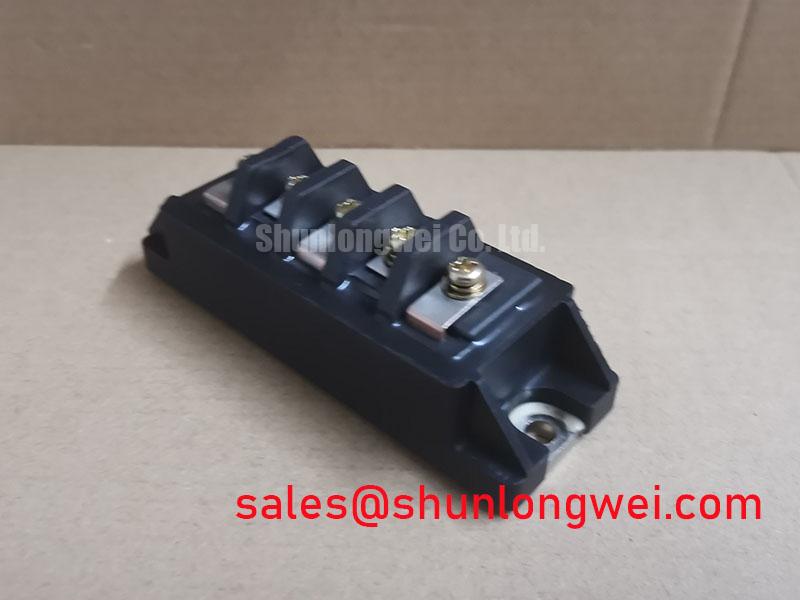
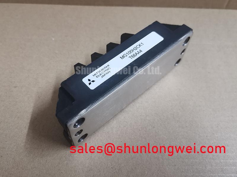
The MG100H2CK1 is an industrial half-bridge N-channel power semiconductor module manufactured by Toshiba. Designed for high-speed switching and motor control applications, it integrates two isolated IGBT cells with high-speed fast recovery freewheeling diodes (FRD) inside a rugged, isolated baseplate package.

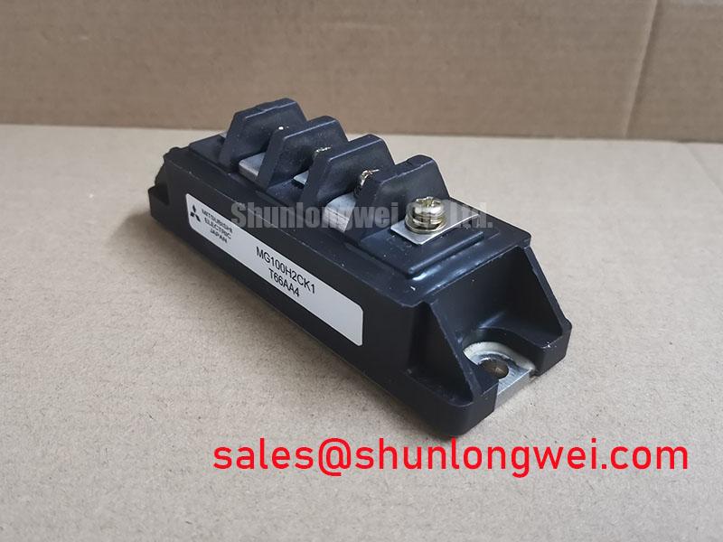
- Core Ratings: 500V Collector-Emitter Voltage ($V_{CES}$), 100A Continuous Collector Current ($I_C$), and 500W maximum power dissipation per element.
- Key Benefits: Low saturation voltage minimizes conduction loss, while the integrated high-speed freewheeling diode suppresses reverse-recovery voltage spikes.
- Thermal Isolation: Electrically isolated baseplates rated up to 2500V AC simplify heatsink mounting without extra insulating washers.
Engineering Analysis & Technical Characteristics
The primary architectural strength of the MG100H2CK1 lies in its balanced half-bridge topology, which houses two matched IGBT dies and inverse diodes within a single thermal envelope. By minimizing internal stray inductance between the upper and lower arms, this configuration restricts voltage overshoot during high-speed turn-off transitions. Circuit designers can explore structural trade-offs in selecting the right IGBT topology: H-Bridge vs Half-Bridge.
Thermal resistance from junction to case ($R_{th(j-c)}$) is held to a maximum of 0.25°C/W for the transistor element. You can think of thermal resistance like pipe friction in a high-volume water pump: a lower resistance value allows generated thermal energy to drain smoothly into the cooling system, preventing hot-spot formation that could compromise gate dielectric integrity.

Additionally, the integrated fast-recovery diodes deliver a typical reverse recovery time ($t_{rr}$) of 0.25 µs. Soft recovery behavior mitigates electromagnetic interference (EMI) during commutations. Engineers evaluating diode-transistor matching can reference how the freewheeling diode dictates system performance for deep-dive optimization insights.
Optimized Application Scenarios
- AC Motor Drives & Variable Frequency Drives (VFDs): Provides stable 100A switching up to 20 kHz for 200V–240V AC line industrial inverters.
- Uninterruptible Power Supplies (UPS): Delivers low forward voltage drop to maximize efficiency in full-bridge inverter stages.
- Induction Heating & Resonant Power Converters: High-speed turn-off characteristics allow zero-voltage switching (ZVS) topologies to operate with minimal power dissipation.
- DC-to-DC Chopper Circuits: Symmetrical two-pack design simplifies busbar routing and current-sharing networks.
System Fit Verdict: The MG100H2CK1 is optimal for 200V–400V DC bus power conversion requiring fast switching and compact dual-pack integration.
Key Electrical & Thermal Specifications
| Parameter | Symbol | Test Conditions | Rating / Value | Unit |
|---|---|---|---|---|
| Collector-Emitter Voltage | $V_{CES}$ | $V_{GE} = 0text{V}, T_j = 25^circtext{C}$ | 500 | V |
| Gate-Emitter Voltage | $V_{GES}$ | $V_{CE} = 0text{V}$ | ±20 | V |
| Collector Current (DC) | $I_C$ | $T_c = 25^circtext{C}$ | 100 | A |
| Forward Diode Current (DC) | $I_F$ | $T_c = 25^circtext{C}$ | 100 | A |
| Collector-Emitter Saturation Voltage | $V_{CE(sat)}$ | $I_C = 100text{A}, V_{GE} = 15text{V}, T_j = 25^circtext{C}$ | 2.7 (typ) / 3.5 (max) | V |
| Diode Forward Voltage Drop | $V_F$ | $I_F = 100text{A}, V_{GE} = 0text{V}$ | 2.3 (typ) / 3.0 (max) | V |
| Turn-off Fall Time | $t_f$ | $V_{CC} = 300text{V}, I_C = 100text{A}, V_{GE} = pm 15text{V}$ | 0.3 (typ) / 0.6 (max) | µs |
| Thermal Resistance (IGBT) | $R_{th(j-c)}$ | Junction to Case, Per IGBT element | 0.25 | °C/W |
| Isolation Voltage | $V_{isol}$ | AC 1 minute, Terminals to Baseplate | 2500 | V |
Engineering FAQ
Q1: What gate driving voltage is recommended for the MG100H2CK1?
A typical forward drive of $+15text{V}$ is recommended to achieve fully saturated conduction and maintain $V_{CE(sat)}$ within the 2.7V typical range. A negative gate bias (such as $-5text{V}$ to $-10text{V}$) is advisable to prevent dv/dt-induced shoot-through in bridge circuits.
Q2: What is the recommended mounting torque for thermal assembly?
The module mounting base screws (M5 or M6 depending on fixture) require a uniform torque between 2.5 N·m and 3.0 N·m. Applying a thin, even layer of thermal interface material (approx. 50–100 µm thickness) ensures optimal heat extraction without mechanical stress.
Q3: Can this module operate at switching frequencies above 20 kHz?
While the MG100H2CK1 features a fast fall time ($t_f approx 0.3,mutext{s}$), switching loss increases linearly with frequency. For operations exceeding 20 kHz, total thermal dissipation ($P_D$) and heatsink thermal capacity must be verified to keep $T_j$ safely below 150°C.
Technical Summary
The Toshiba MG100H2CK1 half-bridge module integrates dual 500V/100A IGBT switches with dedicated fast recovery diodes, offering power electronics engineers a compact, thermally efficient foundation for robust motion control and inverter circuit designs.