Infineon FZ400R12KE3 1200V 400A IGBT Module: Technical Analysis, Specifications, and Applications
FZ400R12KE3 1200V 400A Single IGBT Module Technical Overview
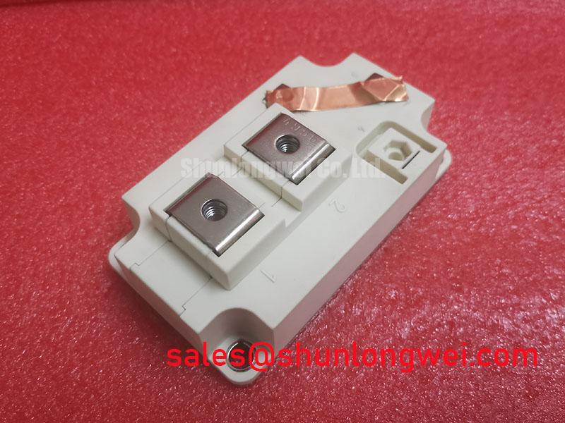
The Infineon FZ400R12KE3 is a 1200V, 400A single-switch IGBT Module engineered for medium-to-high-power industrial conversion systems. Built upon proven Trench/Fieldstop IGBT3 technology paired with an Emitter Controlled diode, this module balances low conduction losses with rugged short-circuit tolerance.
Key Specifications:
- Voltage Rating: 1200V $V_{CES}$
- Continuous DC Collector Current: 400A at $T_C = 80^circtext{C}$ (580A at $T_C = 25^circtext{C}$)
- Saturation Voltage: $V_{CE(sat)} = 1.70text{V}$ typical at $25^circtext{C}$
- Short-Circuit Withstand Time: $10,mutext{s}$ ($V_{GE} le 15text{V}, V_{CC} = 720text{V}, T_{vj} le 125^circtext{C}$)
Engineers deploying power stages in variable frequency drives often face thermal constraints under sustained loading. The FZ400R12KE3 addresses this challenge by delivering predictable on-state losses and a positive temperature coefficient that stabilizes current sharing when modules run in parallel configurations.
Download Official FZ400R12KE3 Datasheet (PDF)



Technical Analysis: Trench/Fieldstop Architecture and Thermal Performance
The core of the FZ400R12KE3 relies on Infineon’s IGBT3 silicon process. By combining a trench-gate structure with an electric field-stop layer, the silicon die minimizes drift-layer thickness without sacrificing breakdown voltage capability. You can trace this structural transition in our guide to trench-gate evolution. This architecture restricts typical on-state saturation voltage to $1.70text{V}$ at room temperature, rising modestly to $1.90text{V}$ at $125^circtext{C}$. This controlled positive temperature shift prevents destructive current runaway when devices run in parallel layouts.
Thermal energy transfer is fundamentally dictated by the module’s junction-to-case thermal resistance ($R_{thJC}$), specified at $0.060,text{K/W}$ for the IGBT switch. One can picture thermal resistance as the constriction within a water pipe: a smaller resistance value represents a broader pipe channel, allowing heat generated in the silicon junction to drain rapidly into the heatsink. Sustained thermal stability requires reviewing transient thermal impedance curves to prevent junction excursions beyond the maximum allowable $150^circtext{C}$ operating point during high-load transients.
Parasitic stray inductances within external bus connections can induce destructive voltage overshoots during fast turn-off transitions. The internal stray inductance ($L_{sCE}$) of the FZ400R12KE3 is measured at $20,text{nH}$. When switching peak collector currents ($I_{CRM} = 800text{A}$), engineers must account for the impact of parasitic inductance by selecting appropriate snubber capacitors or active clamping networks to ensure collector-emitter spikes remain strictly inside the Safe Operating Area ($V_{CES} le 1200text{V}$).
Optimized Application Scenarios
- Industrial Motor Inverters: The 400A continuous rating and standard 62mm footprint make the module suitable for variable frequency drives ranging from 90 kW to 250 kW.
- Central Solar Inverters: Low static losses at elevated operating temperatures ensure conversion efficiency across high-ambient photovoltaic plant environments.
- Uninterruptible Power Supplies (UPS): The 10µs short-circuit withstand rating provides sufficient fault-clearing latency for commercial three-phase emergency power systems.
- High-Power Welding Equipment: Low thermal impedance and robust pulsed current handling ($I_{CRM} = 800text{A}$) support repetitive thermal cycling profiles.
The FZ400R12KE3 represents a verified industry baseline for 1200V/400A conversion requiring low conduction losses and rugged 62mm modular packaging.
Key Specifications Parameter Table
| Parameter Category | Characteristic / Condition | Symbol | Value | Unit |
|---|---|---|---|---|
| Maximum Ratings | Collector-Emitter Voltage ($T_{vj} = 25^circtext{C}$) | $V_{CES}$ | 1200 | V |
| DC Collector Current ($T_C = 80^circtext{C}, T_{vj max} = 150^circtext{C}$) | $I_C$ | 400 | A | |
| Repetitive Peak Collector Current ($t_p = 1,text{ms}$) | $I_{CRM}$ | 800 | A | |
| Total Power Dissipation ($T_C = 25^circtext{C}$, IGBT) | $P_{tot}$ | 2100 | W | |
| Electrical Characteristics | Collector-Emitter Saturation Voltage ($I_C = 400text{A}, V_{GE} = 15text{V}, 25^circtext{C}$) | $V_{CE(sat)}$ | 1.70 (typ) / 2.15 (max) | V |
| Gate Threshold Voltage ($I_C = 16text{mA}, V_{CE} = V_{GE}, 25^circtext{C}$) | $V_{GE(th)}$ | 5.0 (min) – 6.5 (max) | V | |
| Turn-On Energy Dissipation per pulse ($R_{G,on} = 1.8,Omega, 125^circtext{C}$) | $E_{on}$ | 35.0 (typ) | mJ | |
| Turn-Off Energy Dissipation per pulse ($R_{G,off} = 1.8,Omega, 125^circtext{C}$) | $E_{off}$ | 45.0 (typ) | mJ | |
| Thermal & Mechanical | Thermal Resistance, Junction to Case (IGBT) | $R_{thJC}$ | 0.060 | K/W |
| Thermal Resistance, Case to Heatsink ($lambda_{grease} = 1,text{W/m}cdottext{K}$) | $R_{thCH}$ | 0.020 | K/W | |
| Isolation Test Voltage (RMS, $f = 50,text{Hz}, t = 1,text{min}$) | $V_{ISOL}$ | 2.5 | kV |
Engineering FAQ
What is the recommended gate driver voltage for driving the FZ400R12KE3?
The standard gate control voltage is $+15text{V}$ for turn-on to achieve the rated $V_{CE(sat)}$ conduction characteristics, paired with a negative bias of $-5text{V}$ to $-15text{V}$ during turn-off to prevent false triggering from capacitive Miller current.
How should heatsink thermal interface material and mounting torque be managed?
Mounting requires a uniform thermal grease layer of approximately $50,mutext{m}$ to $100,mutext{m}$ thickness. Baseplate mounting screws (M6) must be torqued to $3.0text{ to }6.0,text{Nm}$, while main terminal connections (M6) require $2.5text{ to }5.0,text{Nm}$ to avoid mechanical stress on the internal ceramic substrate.
How does this module differ from high-speed variants like the FZ400R12KS4?
While the fast-switching FZ400R12KS4 module focuses on higher switching frequencies up to several tens of kilohertz, the FZ400R12KE3 prioritizes lower static on-state losses ($V_{CE(sat)}$) and higher short-circuit ruggedness ($10,mutext{s}$), making it better aligned with typical 2 kHz to 8 kHz motor drive switching profiles.
Can two FZ400R12KE3 modules be paralleled directly on the same DC bus?
Yes. Because the Trench IGBT3 die exhibits a positive temperature coefficient at nominal rated current, higher temperatures increase forward drop and naturally balance load current across paralleled modules. Symmetrical busbar routing remains mandatory to ensure balanced stray inductances.
The Infineon FZ400R12KE3 delivers an established standard in high-power conversion, combining a $1.70text{V}$ saturation voltage, $0.060,text{K/W}$ thermal coupling, and proven 62mm mechanical packaging for reliable industrial power electronics implementations. For complementary power conversion parts, browse our full inventory of power semiconductors.