Semikron SKM200GB124D 1200V 200A Half-Bridge IGBT Module: Technical Analysis and Applications
Semikron SKM200GB124D IGBT Module | 1200V 200A Half-Bridge
Product Overview and Engineering Highlights
The Semikron SKM200GB124D is a 1200V, 200A dual IGBT module arranged in a half-bridge topology. It integrates high-speed NPT (Non-Punch-Through) silicon with inverse soft-recovery CAL (Controlled Axial Lifetime) free-wheeling diodes. This architecture delivers robust short-circuit withstand times and a positive temperature coefficient for straightforward module paralleling in high-power industrial converters.

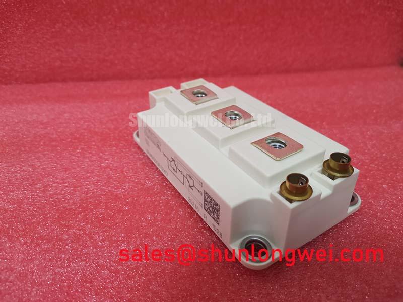
- Core Ratings: 1200V collector-emitter breakdown voltage (VCES), 200A nominal collector current (IC @ Tc=25°C), and typical VCE(sat) of 2.7V at 150A.
- Engineering Advantages: Inherently high short-circuit withstand time (tpsc = 10 µs) and soft-recovery diode characteristics that minimize EMI during high di/dt commutation.
- Design Flexibility: Resolves common thermal runaway challenges in multi-device layouts by enabling natural current balancing through its positive VCE(sat) thermal coefficient.
Technical Analysis and Physical Characteristics
The SKM200GB124D utilizes Semikron’s NPT IGBT technology housed in the industry-standard SEMITRANS 3 package. Unlike punch-through structures that risk negative temperature coefficient behavior at lower currents, this device exhibits a homogeneous silicon structure. Consequently, as the junction heats up, the on-state voltage drop increases slightly. This physical trait acts like a built-in balance scale: warmer parallel dies conduct slightly less current, redistributing energy across companion devices and preventing localized hot-spot formation.
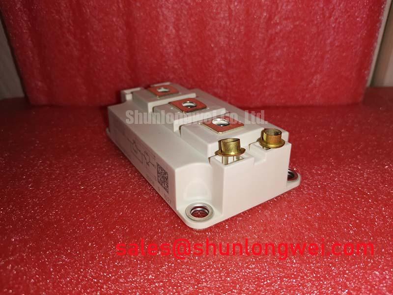


Thermal management relies on a direct copper bonded (DBC) ceramic substrate providing an isolation rating of 2500VAC. The junction-to-case thermal resistance (Rth(j-c)) is rated at 0.16 K/W per IGBT switch. Think of thermal resistance like pipe friction in a plumbing system: lower resistance allows internal dissipation to flow rapidly toward the heatsink, keeping internal die temperatures well beneath the 150°C junction ceiling under sustained loads.
Commutation stability is reinforced by the integrated CAL fast-recovery diode. With reverse recovery times (trr) around 400 ns and soft turn-off waveforms, the diode dampens voltage spikes across parasitic inductances. This reduces the burden on external snubber networks while lowering high-frequency radiated electromagnetic noise in industrial gate driver environments. For deeper insights into module architectures, explore our comparative analysis on PT vs NPT structures and isolated baseplate reliability.
Optimized Application Scenarios
- AC Motor Drives (VFDs): The 10 µs short-circuit withstand time enables standard desaturation detection circuits to shut down safely without device failure during motor phase faults.
- Uninterruptible Power Supplies (UPS): High switching robustness and symmetrical half-bridge configuration simplify three-phase inverter bridge layouts operating between 4 kHz and 12 kHz.
- Welding Power Converters: Low inductive packaging and high pulsed collector current (ICM = 300A) withstand rapid load cycling typical of industrial arc welders. Engineers designing high-stress stages may reference our technical overview on IGBT protection in welding inverters.
- Renewable Energy Inverters: The 1200V blocking voltage provides adequate headroom for 600V to 800V DC bus rails in commercial photovoltaic string units.
Optimal match: Ideal for rugged 400V–480V AC motor drives requiring extended fault tolerance and simple multi-module parallel scalability.
Key Specifications Table
| Parameter Category | Parameter Symbol | Test Conditions | Value / Rating |
|---|---|---|---|
| Absolute Maximum Ratings | VCES | Tvj = 25°C | 1200 V |
| IC | Tc = 25°C (80°C) | 200 A (150 A) | |
| ICM / IFM | tp = 1 ms, Tc = 80°C | 300 A | |
| Electrical Characteristics (IGBT) | VCE(sat) | IC = 150 A, VGE = 15 V, Tvj = 25°C | 2.7 V (typ) / 3.2 V (max) |
| VGE(th) | VCE = VGE, IC = 6 mA | 4.5 V to 6.5 V | |
| tpsc | VCC = 720 V, VGE ≤ 15 V, Tvj ≤ 125°C | 10 µs | |
| Diode Characteristics (CAL) | VF | IF = 150 A, VGE = 0 V, Tvj = 25°C | 2.0 V (typ) / 2.5 V (max) |
| Rth(j-c)D | Per diode element | 0.32 K/W | |
| Thermal & Mechanical | Rth(j-c) | Per IGBT switch | 0.16 K/W |
| Tvj(op) | Operating junction temperature | -40°C to +150°C | |
| Ms / Mt | Mounting torque to heatsink (M5) / terminals (M6) | 3 to 5 Nm / 2.5 to 5 Nm |
Frequently Asked Questions
Q: What gate resistance is recommended for balancing switching loss and overvoltage spikes?
A: The datasheet specifies a minimum internal gate turn-on and turn-off resistance benchmark around 6.8 Ω to 10 Ω at VGE = ±15V. Using higher external resistances smooths collector current fall rates, lowering inductive kickback at the expense of turn-off losses. For layout considerations, see our guide on gate resistor selection.
Q: Can the SKM200GB124D be paralleled directly with other modules?
A: Yes. Because this NPT generation features a positive temperature coefficient of VCE(sat) above nominal currents, current distribution automatically equalizes between parallel modules without requiring tight threshold matching.
Q: What are the assembly torque constraints to avoid baseplate deformation?
A: The module baseplate must be bolted to the heatsink using M5 screws tightened between 3.0 Nm and 5.0 Nm. Thermal paste thickness should remain uniform between 50 µm and 100 µm to avoid mechanical stress and keep thermal resistance within design limits.
The Semikron SKM200GB124D provides industrial equipment designers with an electrically stable, fault-resistant switching platform. By combining NPT silicon stability, robust short-circuit ride-through, and soft-commutation diodes in a standardized footprint, it remains a reliable reference for medium-frequency power electronics.