TT250N18KOF12M1 Thyristor Module: Technical Specifications and Engineering Guide
TT250N18KOF12M1 Thyristor Module Technical Specs
Introduction & Engineering Highlights
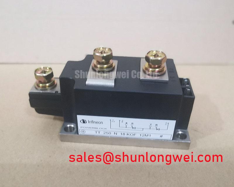
The Infineon TT250N18KOF12M1 is a dual phase-control thyristor module featuring pressure contact technology within an electrically isolated 50mm industrial housing. Designed for line-commutated applications, this module delivers robust blocking voltage margins and dependable power cycling endurance across fluctuating thermal environments.
- Key Parameters: 1800V VDRM/VRRM | 250A ITAVM (@ TC = 85°C) | 9,100A ITSM (10ms, 25°C)
- Operational Advantages: Pressure-contact assembly minimizes thermal fatigue, while the 3000V AC isolated baseplate simplifies heatsink mounting and structural creepage compliance.
- Design Inquiry Solved: Can the TT250N18KOF12M1 safely run directly on 480V to 500V AC industrial lines? Yes, its 1800V repetitive peak rating provides ample safety margin against inductive input line transients without requiring oversized external suppression.
Download Official Datasheet Documentation (PDF)


Technical Analysis Focused on UVP
The structural core of the TT250N18KOF12M1 relies on proven pressure contact technology rather than soldered wire bonds. In conventional power blocks, cyclical thermal expansion produces significant shear stress on soldered interfaces, leading to micro-cracking and eventual bond lift-off. In contrast, pressure contact modules maintain constant mechanical compression over the entire wafer area. This construction mitigates thermal expansion mismatch, extending operational lifetime in harsh cyclic-load operations such as resistance welding and soft-starting.
To understand junction-to-case thermal impedance (RthJC = 0.124 K/W per thyristor), consider thermal resistance as the diameter of a plumbing pipe: a wider diameter allows a massive surge of water to drain without backing up. In semiconductor terms, a lower thermal resistance ensures heat generated inside the silicon quickly transfers to the heat sink, preventing dangerous hot spots during sudden 9.1kA current surges.
Furthermore, managing high dv/dt (1000 V/µs) and di/dt (150 A/µs) demands disciplined board and busbar routing. Designers referencing thyristor dv/dt and di/dt suppression circuit design can implement tailored RC snubber networks. Combined with sister references like the TT250N16KOF or TT250N18KOF series, engineers gain flexibility across varied voltage tiers within our wide catalog of power semiconductors.


Optimized Application Scenarios
- Industrial Soft Starters: The robust I2t rating (414,000 A2s at 25°C) handles locked-rotor induction motor startup currents without semiconductor degradation.
- Electric Heating & Annealing Controls: Phase-angle regulation in heavy furnace power supplies benefits from reliable triggering (IGT ≤ 200mA) and consistent gate drive matching, as discussed in thyristor control in electric furnaces.
- High-Power Static Bypass & UPS Systems: Delivers sub-millisecond line-synchronous transfer capability with an 1800V margin against supply lightning and utility switching transients.
- Controlled Rectifier Front-Ends: Ideal for line-commutated input bridges supplying DC bus systems in industrial process equipment and variable frequency converters.
Best Fit Conclusion: The 1800V rating and pressure contact design make the TT250N18KOF12M1 the standard choice for 400V–500V heavy-duty cyclic AC power control systems.
Key Technical Specifications
| Parameter | Symbol | Test Conditions | Value (Unit) |
|---|---|---|---|
| Repetitive Peak Reverse & Off-State Voltage | VRRM, VDRM | Tvj = -40°C … 130°C | 1800 V |
| Maximum Average On-State Current | ITAVM | TC = 85°C, 180° sin | 250 A |
| Maximum RMS On-State Current | ITRMSM | Continuous conduction | 410 A |
| Surge On-State Current | ITSM | 10 ms, Tvj = 25°C / 130°C | 9,100 A / 8,000 A |
| Surge Current Capability | I2t | 10 ms, Tvj = 25°C / 130°C | 414,000 / 320,000 A2s |
| Gate Trigger Current | IGT | Tvj = 25°C, VD = 12V | ≤ 200 mA |
| Gate Trigger Voltage | VGT | Tvj = 25°C, VD = 12V | ≤ 2.0 V |
| Critical Rate of Rise of Off-State Voltage | (dv/dt)cr | Tvj = 130°C, VD = 0.67 VDRM | 1000 V/µs |
| Thermal Resistance, Junction to Case | RthJC | Per thyristor / per module | 0.124 / 0.062 K/W |
| RMS Isolation Test Voltage | VISOL | 50 Hz, 1 min / 1 sec | 3.0 kV / 3.6 kV |
Engineering FAQ
What mounting torque is required for the TT250N18KOF12M1 baseplate and power terminals?
The baseplate heatsink mounting torque (M1) requires a tightening force of 5 Nm (±15%), while the M8 electrical main terminals (M2) specify 9 Nm (±10%). Maintaining uniform torque prevents module deformation and preserves balanced internal contact pressure.
How do I size a thermal heatsink for this module under rated 250A average load?
Total conduction loss per module at continuous load is approximately 600W. Using RthJC = 0.062 K/W and thermal interface grease (RthCH ≈ 0.02 K/W), maintaining junction temperature below 120°C in a 40°C ambient enclosure requires an active heatsink rating of RthHA ≤ 0.05 K/W.
What gate trigger circuit characteristics does the module require?
Reliable turn-on requires a gate current pulse amplitude of at least 0.8A to 1.5A with a rise time under 1 µs, particularly when operating near maximum rated critical di/dt conditions (150 A/µs).
Does this module offer internal electrical isolation?
Yes, the copper baseplate features direct bonded ceramic isolation capable of withstanding 3000V AC for one minute, permitting multiple modules to be mounted on a common grounded heatsink.
Design Integration Summary
The TT250N18KOF12M1 provides a balanced combination of 1800V blocking margin, pressure contact reliability, and standard 50mm package dimensions. For engineers designing medium-voltage industrial converters, soft starters, or resistance heating controls, this module ensures predictable thermal behavior and long service intervals across demanding duty cycles.