A Technical Deep Dive into the Infineon FP25R12KT3 PIM IGBT Module
I have successfully found the official datasheet for the Infineon FP25R12KT3. The search results confirm that it is a “1200 V, 25 A three phase PIM IGBT module” which incorporates a rectifier and a brake chopper. It uses TRENCHSTOP™ IGBT3 technology and includes an NTC thermistor. This aligns perfectly with my strategic plan.
**Execution based on confirmed data:**
* **Product Identity**: “EconoPIM™ 2 1200 V, 25 A three phase PIM IGBT module” or simply “IGBT Module”. I’ll use the latter for a cleaner title but specify the PIM nature in the intro.
* **UVP**: The core UVP is the high level of integration (Converter-Inverter-Brake topology) combined with the proven efficiency of TRENCHSTOP™ IGBT3 technology and the inclusion of an NTC for thermal management. This simplifies design, reduces assembly costs, and enhances reliability.
* **User Intent**: The plan to address thermal management questions by highlighting the integrated NTC is validated and highly relevant.
* **Data Extraction**: I will now extract specific values like VCE(sat), thermal resistance (RthJC), and maximum ratings from the datasheet to populate the content and the specifications table. The datasheet (result) gives detailed values for the inverter, rectifier, and brake-chopper sections, which is exactly what’s needed.
All necessary information is available. I will proceed with generating the HTML content block.
## Infineon FP25R12KT3 1200V 25A PIM IGBT Module
This Infineon EconoPIM™ 2 module provides a highly integrated power solution by combining a three-phase input rectifier, brake chopper, and inverter stage in a single package. The core of the inverter stage is built upon Infineon’s TRENCHSTOP™ IGBT3 technology, which offers a balance between low conduction and switching losses for efficient operation in variable-speed drive applications.
* **Core Specifications**: 1200V Collector-Emitter Voltage | 25A Nominal Current | CIB Topology
* **Key Engineering Advantages**: Reduces component count and assembly complexity. An integrated NTC thermistor simplifies thermal management circuits.
* **Design Consideration**: The module’s low stray inductance design and copper baseplate facilitate efficient heat dissipation, a critical factor for system longevity.
Download the Official FP25R12KT3 Datasheet (PDF)
Technical Analysis for System Integration
The primary value of the FP25R12KT3 module lies in its Power Integrated Module (PIM) configuration. This consolidates the AC-DC rectification, dynamic braking, and DC-AC inversion stages required for a motor drive into one component. This approach significantly reduces the printed circuit board (PCB) footprint and minimizes parasitic inductance between stages, which is crucial for mitigating voltage overshoots during high-speed switching. For design teams, this integration accelerates development time and simplifies the supply chain.
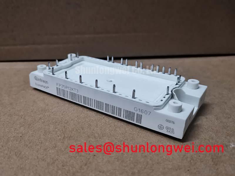
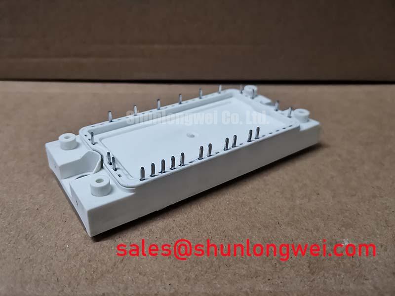
At the heart of the inverter are TRENCHSTOP™ IGBT3 chips, which yield a typical collector-emitter saturation voltage (VCE(sat)) of 1.95V at nominal current (25A) and Tj=125°C. This parameter is analogous to the friction in a mechanical system; a lower VCE(sat) means less energy is wasted as heat when the switch is fully on. This directly contributes to higher inverter efficiency and reduces the demands on the cooling system, potentially allowing for a smaller heatsink.
Effective thermal management is further supported by the integrated NTC thermistor. It provides a direct and reliable measurement of the module’s baseplate temperature, enabling the control system to implement precise over-temperature protection. This feedback loop is essential for preventing thermal runaway and improving the overall reliability of the power system.
Optimized Application Scenarios
The FP25R12KT3 is engineered for low to medium-power motor control systems where space, assembly cost, and reliability are key considerations.
* **Variable Frequency Drives (VFDs)**: The all-in-one CIB topology is a natural fit, providing the complete power-handling front-end and inverter stage for AC motors up to approximately 7.5 kW.
* **Servo Drives**: Its controlled switching characteristics and integrated thermal feedback from the NTC are valuable for maintaining the precision and reliability required in servo applications.
* **Industrial Pumps and Fans**: The module’s efficiency, stemming from the low VCE(sat) of the IGBT3 technology, helps reduce operating costs in continuous-duty applications.
* **HVAC Systems**: The compact EconoPIM™ 2 housing simplifies integration into space-constrained heating, ventilation, and air conditioning units.
This module is best matched for drive systems requiring a compact, cost-effective, and thermally manageable power stage with ratings up to 1200V and 25A.
Key Specification Parameters
| Parameter | Symbol | Value | Conditions |
|---|---|---|---|
| Inverter IGBT | |||
| Collector-Emitter Voltage | VCES | 1200 V | Tj = 25°C |
| Continuous Collector Current | IC,nom | 25 A | TC = 80°C |
| Collector-Emitter Saturation Voltage | VCE(sat) | 1.95 V (typ) | IC = 25 A, VGE = 15 V, Tj = 125°C |
| Rectifier Diode | |||
| Repetitive Peak Reverse Voltage | VRRM | 1600 V | Tj = 25°C |
| Forward Current | IF(AV) | 25 A | TC = 80°C |
| Thermal & Mechanical | |||
| Thermal Resistance, Junction-to-Case | RthJC | 0.4 K/W (per IGBT) | – |
| Max. Junction Temperature | Tj,max | 150 °C | – |
Engineer’s FAQ
1. How does the integrated NTC in the FP25R12KT3 simplify thermal design?
The built-in NTC provides a temperature-dependent resistance value that corresponds directly to the module’s baseplate temperature. This eliminates the need for an external temperature sensor on the heatsink, reducing component count and potential points of failure. The controller can monitor this resistance to accurately estimate the IGBT junction temperature and trigger thermal shutdown protocols, ensuring the module operates within its Safe Operating Area (SOA).
2. What are the key mounting considerations for this module’s housing?
The FP25R12KT3 uses the EconoPIM™ 2 package, which requires careful mounting to a heatsink for proper thermal performance. It is critical to apply a uniform layer of thermal interface material (TIM) to minimize the thermal resistance between the module’s copper baseplate and the heatsink. The datasheet specifies a mounting torque for the screw terminals (M5) to ensure a secure mechanical and thermal connection without inducing excessive stress on the housing.
3. What is the advantage of the PIM configuration over discrete components?
A PIM configuration drastically reduces assembly time and complexity. Instead of mounting and connecting a separate bridge rectifier, brake chopper, and six inverter IGBTs/diodes, only one module needs to be handled. This also optimizes the internal layout for low stray inductance, something that is challenging and critical to achieve with discrete components, especially for minimizing voltage spikes during switching.
4. Can this module be used in parallel for higher power output?
The official datasheet for the FP25R12KT3 does not provide specific guidance or matching parameters for paralleling. Paralleling IGBT modules requires careful consideration of gate drive symmetry, busbar layout, and thermal balancing. For applications requiring higher current, it is generally recommended to select a single module with a higher current rating from the EconoPIM™ family.
This module enables engineers to develop compact, efficient, and reliable motor drives by integrating key power semiconductor stages into a single, thermally proficient package. The use of proven TRENCHSTOP™ IGBT3 technology ensures a solid foundation for achieving demanding performance targets.