An Engineer’s Guide to the Toshiba MG75Q2YS50 IGBT Module
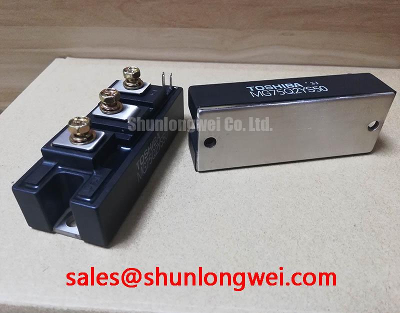
Toshiba MG75Q2YS50 1200V 75A Dual IGBT Module
Introduction to a Robust Half-Bridge Power Solution
The Toshiba MG75Q2YS50 is a Silicon N Channel IGBT module that integrates a complete half-bridge circuit into a single, robust package. This device is engineered to provide a reliable foundation for high-power switching applications, delivering a balanced profile of voltage endurance, current handling, and switching speed. Its core value proposition is the simplification of power stage design by providing a proven, high-voltage building block for inverters and converters.
- Core Specifications: 1200V | 75A | VCE(sat) 3.0V (typ)
- Key Advantages: Integrated half-bridge configuration simplifies inverter leg design. High voltage rating provides a significant safety margin for industrial systems.
For engineers designing systems like variable frequency drives (VFDs), this module offers a dependable component that balances conduction and switching losses effectively.
Download the Official MG75Q2YS50 Datasheet (PDF)

Technical Analysis: Engineering for Reliability
The MG75Q2YS50 is built around a collector-emitter voltage (Vces) rating of 1200V. This high blocking voltage is essential for applications connected to 400V or 480V three-phase AC lines, providing the necessary headroom to withstand voltage spikes and transients common in industrial environments. The module’s internal half-bridge, or dual-switch, configuration is the fundamental circuit for building two-level inverters, reducing the need for complex busbar arrangements and simplifying the overall mechanical layout of the power conversion system.
A critical aspect of its performance is the collector-emitter saturation voltage (Vce(sat)), specified at a typical value of 3.0V at the rated current of 75A. This parameter directly determines the power lost as heat during the IGBT’s on-state. While newer technologies may offer lower values, the MG75Q2YS50 provides a deliberate balance between these conduction losses and its switching performance. Its specified typical turn-off time (toff) of 0.90 µs is suited for medium-frequency operation, typically up to 20 kHz, ensuring controlled switching behavior and minimizing electromagnetic interference (EMI). Effective thermal management is crucial, and the device’s thermal resistance plays a key role. Think of the junction-to-case thermal resistance (Rth(j-c)) like the width of a pipe draining heat from the active silicon. The specified value of 0.24 °C/W for the IGBT ensures an effective path for heat to travel to the heatsink, which is vital for maintaining reliability under continuous load.
Optimized Application Scenarios
The specific characteristics of the MG75Q2YS50 make it a strong fit for several demanding applications:
- Industrial Motor Drives: The 1200V rating and 75A current capability are ideal for controlling three-phase AC motors. The integrated half-bridge is used to construct each phase of the drive’s inverter stage.
- Uninterruptible Power Supplies (UPS): Its robust voltage rating and proven reliability are critical for the main inverter stage in online UPS systems, ensuring stable power for critical equipment.
- Welding Power Supplies: The module is capable of handling the high-current, pulsed operation required in inverter-based welders, with its thermal design supporting repetitive cycling.
- Renewable Energy Systems: Suitable for the DC-AC conversion stage in solar and wind inverters where high DC bus voltages are standard.
This module is a best-match for medium-frequency power conversion systems where a durable, field-proven, and easily integrated half-bridge solution is required.
Key Specification Parameters for MG75Q2YS50
| Parameter | Symbol | Value | Unit |
|---|---|---|---|
| Absolute Maximum Ratings (Tc=25°C) | |||
| Collector-Emitter Voltage | VCES | 1200 | V |
| Gate-Emitter Voltage | VGES | ±20 | V |
| Collector Current (DC) | IC | 75 (Tc=25°C), 50 (Tc=80°C) | A |
| Collector Power Dissipation (per IGBT) | PC | 520 | W |
| Electrical Characteristics (Tj=25°C unless otherwise noted) | |||
| Collector-Emitter Saturation Voltage (IC=75A) | VCE(sat) | 3.0 (Typ), 3.6 (Max) | V |
| Gate-Emitter Leakage Current | IGES | ±500 | nA |
| Turn-Off Time | toff | 0.90 (Typ) | µs |
| Diode Forward Voltage (IF=75A) | VECF | 2.5 (Typ), 3.2 (Max) | V |
Engineer’s Frequently Asked Questions
- What is the recommended gate drive voltage for the MG75Q2YS50?
- The datasheet specifies the electrical characteristics based on a gate-emitter voltage (VGE) of +15V for turn-on and typically recommends a 0V or negative voltage for secure turn-off. A standard +15V/-5V to +15V/-15V gate drive is common practice to ensure fast turn-off and high noise immunity. Referencing a guide on robust gate drive design is advisable.
- How critical is thermal management for this module?
- Thermal management is essential. The module’s maximum power dissipation is 520W per IGBT. To operate reliably, a properly sized heatsink and the correct application of thermal interface material (TIM) are required to keep the junction temperature below the 150°C maximum rating. Inadequate cooling is a primary cause of device failure.
- What is the function of the integrated free-wheeling diode (FWD)?
- The FWD provides a path for the inductive load current to flow when the IGBT is switched off. This is crucial in motor drive and inverter applications. The MG75Q2YS50 includes an FWD matched to the IGBT’s performance, which is vital for preventing damaging voltage overshoots and ensuring efficient energy recirculation.
- Can multiple MG75Q2YS50 modules be paralleled for higher current?
- While paralleling IGBT modules is possible, it requires careful design to ensure proper current sharing. Factors like VCE(sat) and gate threshold voltage matching, along with a symmetrical busbar layout, are critical. The datasheet for the MG75Q2YS50 does not provide specific guidance on paralleling, so any such implementation must be thoroughly validated by the design engineer.
Enabling Reliable Power Conversion
The Toshiba MG75Q2YS50 provides a dependable and straightforward solution for implementing a high-voltage power stage. By integrating a half-bridge circuit into a standard industrial package, it allows engineers to focus on system-level goals, confident in the performance of the core switching component. Its balanced electrical and thermal characteristics support the creation of durable and efficient power conversion systems for a wide range of industrial machinery.