BSM10GD120DN2: A Technical Analysis of the 1200V Dual Chopper IGBT Module
BSM10GD120DN2 | 1200V 10A Dual Chopper IGBT Module
Introduction and Core Highlights
The Infineon BSM10GD120DN2 is a robust IGBT power module featuring a dual chopper configuration, providing a versatile and reliable solution for industrial power conversion applications. This module integrates two IGBTs with corresponding freewheeling diodes and an NTC thermistor, all within an industry-standard package with an insulated metal baseplate. This design offers significant flexibility for implementing various power topologies, such as buck or boost converters, from a single component.
- Core Specifications: 1200V Collector-Emitter Voltage | 10A DC Collector Current (@ TC=80°C) | Integrated NTC Thermistor
- Key Advantages: Facilitates flexible power stage designs, simplifies thermal management through integrated sensing.
Download Official Datasheet (PDF)

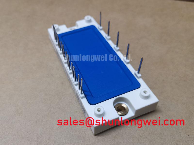
Technical Analysis of Core Features
The engineering value of the BSM10GD120DN2 module is rooted in its highly functional integration and robust electrical characteristics. The dual chopper (or half-bridge) topology is a primary differentiator, offering two independent switching units in one package. This inherent flexibility allows design engineers to implement two independent DC-DC buck converters, a single boost converter, or other custom switching circuits without sourcing multiple discrete components. This simplifies PCB layout, reduces assembly complexity, and can improve the power density of the final system.
Reliability is further enhanced by the inclusion of an NTC thermistor. This component provides a direct and accurate method for monitoring the module’s internal operating temperature. Think of the module’s thermal resistance (RthJC) as a pipeline for heat; a lower value means a wider pipe, allowing heat to escape more efficiently. The BSM10GD120DN2 has a specified RthJC of 1.0 K/W per IGBT, a critical parameter for heatsink design. By monitoring the NTC, a control system can anticipate and prevent overheating conditions, thereby extending the operational life of both the module and the end equipment. For a deeper understanding of this topic, review this guide on the critical role of the integrated NTC.
Optimized Application Scenarios
The electrical ratings and configuration of this module make it well-suited for a range of industrial power systems. Its performance characteristics are a strong fit for the following applications:
- DC-DC Converters: The dual chopper arrangement is fundamentally designed for buck, boost, and buck-boost converter topologies.
- Small Industrial Motor Drives: The 1200V/10A rating is sufficient for controlling low-power AC induction motors or DC motors in factory automation.
- Switched-Mode Power Supplies (SMPS): The high voltage rating provides a substantial safety margin for offline power supplies operating from 230V to 480V AC lines.
- Battery Charging Systems: Can be used to control the charging current and voltage for industrial battery systems with high efficiency.
This module is an optimal match for low-to-medium power systems where configuration flexibility and robust thermal performance are primary design drivers.
Key Specification Parameters for BSM10GD120DN2
| Absolute Maximum Ratings (TC = 25°C unless otherwise specified) | ||
|---|---|---|
| Parameter | Symbol | Value |
| Collector-Emitter Voltage | VCES | 1200 V |
| DC Collector Current (TC = 80°C) | IC | 10 A |
| Repetitive Peak Collector Current (tP = 1 ms) | ICRM | 20 A |
| Gate-Emitter Voltage | VGES | ±20 V |
| Total Power Dissipation (per IGBT) | Ptot | 125 W |
| Max. Junction Temperature | Tvj max | 150 °C |
| Isolation Test Voltage (RMS, 50 Hz, 1 min.) | Visol | 2500 V |
Engineer’s FAQ
- What are the main advantages of the dual chopper configuration in the BSM10GD120DN2?
- The dual chopper topology provides two independent IGBT and diode pairs. This allows engineers to use a single module to build a half-bridge inverter, two separate buck converters for independent DC outputs, or a single boost converter, offering significant design flexibility and reducing component count.
- What is the recommended mounting torque, and why is it important?
- The datasheet specifies a mounting torque of 3.0 Nm for the M5 module mounting screws and 1.5 Nm for the M4 terminal screws. Applying the correct torque is critical. Insufficient torque leads to high thermal and electrical resistance, causing overheating. Excessive torque can damage the module’s baseplate and internal ceramic substrate, compromising isolation and leading to premature failure.
- How should the integrated NTC thermistor be used?
- The NTC thermistor provides a resistance that changes predictably with temperature. It should be connected to a monitoring circuit, typically using a voltage divider and an ADC input on a microcontroller. By referencing the resistance-temperature characteristic curve in the datasheet, the control system can accurately measure the module’s baseplate temperature and trigger alarms or shutdown procedures if it exceeds safe limits.
- What is the typical collector-emitter saturation voltage (VCEsat)?
- According to the datasheet, the typical VCEsat is 3.75V at a collector current of 10A and a junction temperature of 125°C. This value is essential for accurately calculating conduction losses in the system, which directly impacts overall efficiency and heatsink requirements.
Enabling Reliable Power Design
The BSM10GD120DN2 offers a straightforward and dependable platform for power electronics engineers. By combining a flexible dual-switch topology with the essential safety feature of an integrated NTC thermistor, this module enables the development of robust and thermally stable power conversion systems. Its adherence to a standard industrial footprint also ensures ease of integration and mechanical compatibility in a wide variety of designs. This makes it a practical choice for developing efficient low and high-frequency inverters and converters.