Comprehensive Technical Overview of the Infineon FZ600R12KE3 1200V 600A IGBT Module
FZ600R12KE3 Infineon Single IGBT Module | 1200V 600A Trench/Fieldstop
High-Current Efficiency with 1200V TrenchGate Technology
The FZ600R12KE3 is a high-performance single IGBT module utilizing Infineon’s established IGBT3 Trench/Fieldstop technology. Rated at 1200V and 600A, this module is engineered for demanding industrial power conversion where conduction losses must be minimized without compromising switching speed. By integrating a low $V_{CE(sat)}$ of 1.70V, it addresses the common engineer concern regarding system efficiency in high-power motor drives and renewable energy converters.
- Core Specifications: 1200V Blocking Voltage | 600A Continuous DC Collector Current | 1.70V Typical Saturation Voltage.
- Technical Advantages: Exceptional short-circuit ruggedness of 10μs and optimized thermal resistance for high power density.
- Design Efficiency: The TrenchGate structure facilitates a lower VCE(sat), directly reducing the cooling requirements for the overall system.
Download FZ600R12KE3 Official Datasheet (PDF)
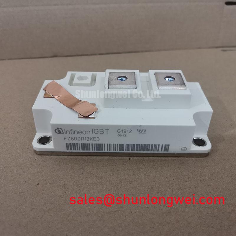

Technical Analysis of Loss Reduction and Thermal Dynamics
The engineering value of the FZ600R12KE3 lies in its balance between static and dynamic losses. Utilizing Infineon TRENCHSTOP™ IGBT3 technology, the device achieves a vertical Fieldstop structure that controls the electric field distribution. This results in a “soft” switching behavior, which significantly reduces electromagnetic interference (EMI) and voltage overshoots during turn-off transients.
Thermal management is equally critical for the longevity of power semiconductors. To understand the importance of the module’s low junction-to-case thermal resistance ($R_{thJC}$), one can imagine thermal resistance as the width of a drainage pipe. A lower value means heat—the “water” in this analogy—can flow away from the silicon die much faster, preventing the temperature spikes that lead to catastrophic failures. The FZ600R12KE3 features a copper baseplate optimized for efficient heat transfer to the heatsink.


Optimized Application Scenarios
The robust electrical characteristics of this module make it suitable for high-power industrial environments:
- Variable Frequency Drives (VFD): The 600A current handling allows for efficient motor control in heavy-duty machinery where high torque and reliability are non-negotiable.
- Solar Inverters: The low conduction losses associated with IGBT3 technology maximize the yield of megawatt-scale PV plants.
- Uninterruptible Power Supplies (UPS): Fast switching capability ensures high output power quality and rapid response to grid fluctuations.
- Welding Equipment: High short-circuit ruggedness provides a safety margin against the aggressive load transients typical in industrial welding.
Best Match Conclusion: The FZ600R12KE3 is ideal for 1200V systems requiring high reliability and low thermal overhead in high-current industrial switching applications.
FZ600R12KE3 Key Specifications
| Parameter Group | Description | Value (Typical) |
|---|---|---|
| Maximum Ratings | Collector-Emitter Voltage ($V_{CES}$) | 1200 V |
| Continuous DC Collector Current ($I_C$) | 600 A ($T_C = 80^circ C$) | |
| Repetitive Peak Collector Current ($I_{CRM}$) | 1200 A | |
| Electrical Characteristics | Gate Threshold Voltage ($V_{GE(th)}$) | 5.0V to 6.5V |
| Collector-Emitter Saturation Voltage | 1.70 V ($T_{vj} = 125^circ C$) | |
| Input Capacitance ($C_{ies}$) | 43 nF | |
| Thermal Properties | Thermal Resistance, Junction to Case | 0.043 K/W |
| Operating Junction Temperature ($T_{vjtext{ op}}$) | -40 to +125 °C |
Engineer FAQ
Q1: How do I calculate the total power dissipation for the FZ600R12KE3 in a steady-state inverter design?
A: Total dissipation is the sum of conduction losses ($P_{cond} = V_{CE(sat)} times I_C$) and switching losses ($P_{sw} = (E_{on} + E_{off}) times f_{sw}$). Use the 125°C parameters from the datasheet for a realistic thermal safety margin.
Q2: What is the recommended gate resistor value ($R_G$) for optimizing switching speed vs. EMI?
A: The datasheet specifies a typical $R_{Gtext{ on/off}}$ of 1.2Ω. Increasing this value will soften the switching and reduce EMI but will increase switching energy losses. Balancing this is critical to avoid premature IGBT burnout.
Q3: Is negative gate voltage required for turn-off?
A: While not strictly required for operation, applying a negative bias (e.g., -5V to -15V) is highly recommended in 600A modules to prevent parasitic turn-on caused by high $dv/dt$ transients across the Miller capacitance.
The FZ600R12KE3 represents a robust solution for high-power switching, combining the efficiency of the IGBT3 architecture with proven package reliability. Engineers can leverage its low conduction losses and high short-circuit tolerance to design compact, resilient conversion stages for modern industrial power systems.