Eupec F4-75R12KS4 1200V 75A Four-Pack IGBT Module: Technical Overview and Application Guide
Eupec F4-75R12KS4 1200V 75A EconoPACK™ 2 Four-Pack IGBT Module
The Eupec F4-75R12KS4 is a high-performance power semiconductor module featuring a specialized four-pack configuration, designed for precision power conversion in a compact EconoPACK™ 2 housing. This module provides a fully integrated H-bridge solution, delivering 1200V isolation and 75A continuous collector current, making it a robust building block for four-quadrant operation and high-frequency switching environments. By integrating four IGBTs and their corresponding freewheeling diodes into a single footprint, it significantly enhances power density while reducing parasitic inductance compared to discrete solutions.
- Core Specifications: 1200V Blocking Voltage | 75A Collector Current (at 80°C) | VCE(sat) 2.10V (Typical).
- Key Engineering Advantages: Optimized for reduced switching losses and simplified thermal management through a low-profile housing.
- Design Application: Often utilized in systems requiring bi-directional energy flow where high-speed switching is necessary to maintain system efficiency.
Download Official F4-75R12KS4 Datasheet (PDF)
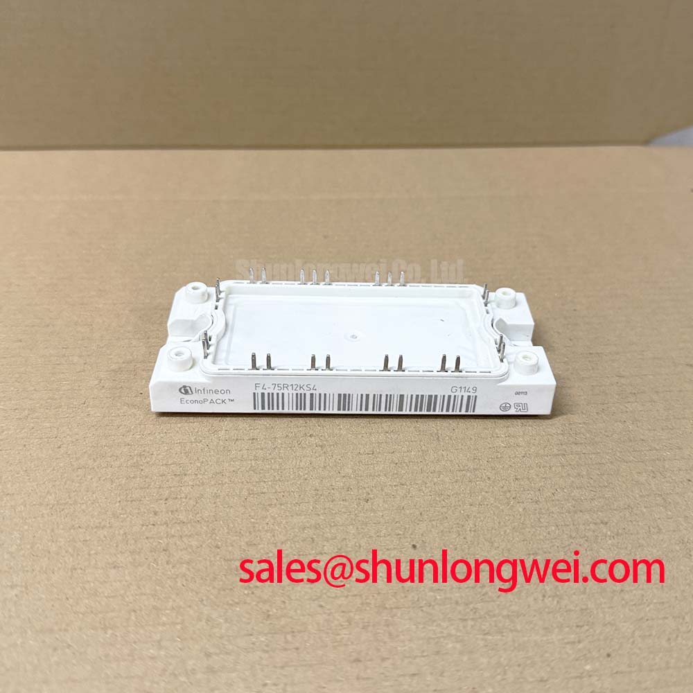
Four-Pack Topology and Switching Efficiency Analysis
The F4-75R12KS4 distinguishes itself through its internal topology. Unlike standard six-pack modules used for three-phase inverters, the “Four-Pack” or H-bridge arrangement is specifically tailored for DC/AC conversion in single-phase systems or DC/DC conversion in high-power applications. According to the manufacturer data, the KS4 series utilizes a Trench/Fieldstop chip technology optimized for faster switching transients without excessive voltage overshoots. This characteristic is vital when designers transition to higher carrier frequencies to reduce the size of passive components like inductors and capacitors.

Thermal management for this module relies on the low thermal resistance between the junction and the baseplate (RthJC). To conceptualize this, one can imagine thermal resistance as the width of an exhaust pipe; a lower value (wider pipe) allows heat to flow away from the silicon die much more effectively, preventing the “thermal bottleneck” that leads to catastrophic device failure during high-load surges. With a rated RthJC of approximately 0.25 K/W for the IGBT part, the F4-75R12KS4 allows for high power throughput in relatively small enclosures.
Optimized Application Scenarios
The technical profile of the F4-75R12KS4 makes it particularly effective in the following industrial contexts:
- High-Frequency Solar Inverters: The fast switching speed of the IGBT3/4 chips reduces efficiency losses during peak sunlight hours.
- Uninterruptible Power Supplies (UPS): Its integrated H-bridge design ensures consistent performance during power transition states.
- Servo Drive Systems: Provides precise control for single-phase motor segments or regenerative braking units.
- Medical Imaging Power Stages: High voltage stability (1200V) and low EMI noise support sensitive diagnostic equipment environments.
This module is the optimal match for industrial designs requiring a compact, integrated bridge solution with a focus on high-frequency switching efficiency.


F4-75R12KS4 Key Technical Specifications
| Parameter Group | Characteristic | Value (Typical/Max) |
|---|---|---|
| Absolute Maximums | Collector-Emitter Voltage (VCES) | 1200 V |
| Continuous DC Collector Current (IC) | 75 A (at TC=80°C) | |
| Repetitive Peak Collector Current | 150 A | |
| Electrical (at 25°C) | Collector-Emitter Saturation Voltage | 2.10 V (at IC=75A) |
| Gate Threshold Voltage (VGEth) | 5.8 V (Typical) | |
| Input Capacitance (Cies) | 5.3 nF | |
| Thermal Properties | IGBT Thermal Resistance (RthJC) | 0.25 K/W |
Engineer FAQ: Implementation and Reliability
Q: How does the F4-75R12KS4 handle high-frequency carrier cycles in solar applications?
A: This module belongs to the KS4 family, which is specifically characterized for lower switching losses (Eon/Eoff). When integrated with intelligent IGBT drivers, it maintains high efficiency at switching frequencies where standard modules might encounter thermal runaway due to accumulation of switching energy.
Q: What are the primary thermal design considerations for the EconoPACK™ 2 housing?
A: Uniform pressure distribution across the baseplate is essential. Engineers should follow specific torque requirements (typically 3Nm to 6Nm for mounting screws) to ensure optimal contact with the heatsink. For detailed thermal modeling, refer to our guide on IGBT thermal design and Zth curves.
Q: Is this module suitable for harsh environmental conditions?
A: The F4-75R12KS4 features a high-reliability internal insulation (Visol = 2.5 kV AC). However, long-term reliability in humid or high-vibration industrial environments depends heavily on the use of insulating silicone gels and proper external sealing within the power electronics enclosure.
The Eupec F4-75R12KS4 provides a streamlined, high-density power switching solution that empowers engineers to architect efficient H-bridge systems. By prioritizing low saturation voltages and optimized thermal flow, this module remains a reliable choice for modern industrial power conversion demands.