Exploring the Infineon FZ600R17KE3: A Robust 1700V 600A Single IGBT Module for High-Power Industrial Applications
FZ600R17KE3 | Infineon 1700V 600A Single IGBT Module
Introduction and Core High-Power Capabilities
The FZ600R17KE3 is an industry-standard Single IGBT module engineered by Infineon, utilizing the mature Trench/Fieldstop IGBT3 architecture. This module is a cornerstone for high-power industrial applications that demand a rigorous balance between efficiency and high-voltage stability. By optimizing the carrier concentration through its trench structure, the FZ600R17KE3 provides engineers with a robust solution for energy-intensive environments where reliability is non-negotiable.
- Core Specifications: 1700V | 600A | $V_{CE(sat)}$ 2.0V (Typical)
- Key Advantages: Low saturation voltage for reduced conduction losses and an integrated free-wheeling diode with soft recovery characteristics.
- Design Efficiency: Specifically addresses the common engineering challenge of “how to improve efficiency in 1700V systems” by minimizing the conduction-to-switching loss ratio in high-voltage converters.
Download Official FZ600R17KE3 Datasheet (PDF)
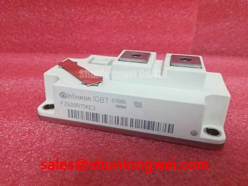
Technical Analysis of Trench/Fieldstop IGBT3 UVP
The Unique Value Proposition (UVP) of the FZ600R17KE3 lies in its IGBT3 Trench/Fieldstop technology. Unlike older planar structures, the trench gate significantly reduces the cell pitch, which allows for a much higher current density while lowering the collector-emitter saturation voltage ($V_{CE(sat)}$). For the system designer, this means conduction losses are kept to a minimum even when the module is operating at its rated 600A. When compared to newer generations like IGBT4, the IGBT3 KE3 series remains a preferred choice for applications where the 1700V blocking capability must be paired with extreme ruggedness against short circuits.
Thermal management is a critical factor in the longevity of the FZ600R17KE3. You can think of the thermal resistance ($R_{thJC}$) as the width of a drainage pipe; a lower value means heat can flow away from the sensitive silicon junction much faster, preventing the “flooding” effect of thermal runaway. With a $R_{thJC}$ of 0.032 K/W for the IGBT part, this module ensures that high power can be switched without exceeding the maximum junction temperature of $125^circ C$, provided the cooling system is correctly sized. Engineers must also account for parasitic inductance during layout, as the 1700V rating leaves less margin for voltage spikes during high $di/dt$ events.
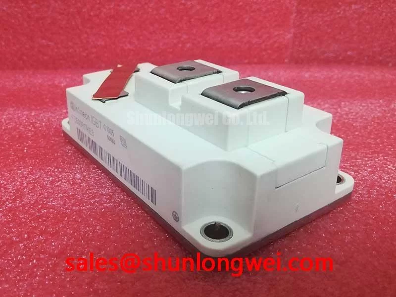
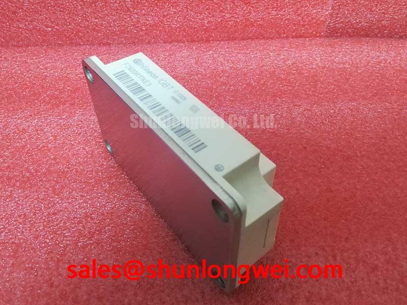
Optimized Application Scenarios
- Traction Drives (Rail): The 1700V blocking voltage provides the necessary safety margin for overhead line fluctuations in rail systems.
- Medium Voltage Industrial Drives: Low conduction losses make it ideal for variable frequency drives (VFDs) where the module remains in the “on” state for long periods.
- Wind Turbine Converters: High power density allows for compact converter designs in the nacelle where space is at a premium.
- Uninterruptible Power Supplies (UPS): The soft-recovery diode minimizes EMI, reducing the filtering requirements in high-power UPS stages.
Best Match Conclusion: The FZ600R17KE3 is the optimal choice for 1700V systems requiring 600A throughput where thermal stability and conduction efficiency take priority over ultra-high switching frequencies.
Key Specifications Table
| Parameter | Condition | Value |
|---|---|---|
| $V_{CES}$ (Collector-Emitter Voltage) | $T_j = 25^circ C$ | 1700V |
| $I_{C, nom}$ (Continuous DC Current) | $T_C = 80^circ C$ | 600A |
| $V_{CE(sat)}$ (Saturation Voltage) | $I_C = 600A, V_{GE} = 15V$ | 2.00V (typ) |
| $t_{sc}$ (Short Circuit Withstand Time) | $V_{GE} le 15V, V_{CC} = 1000V$ | 10 $mu s$ |
| $R_{thJC}$ (Thermal Resistance) | Per IGBT | 0.032 K/W |
Engineer FAQ
Q1: What is the recommended gate voltage for switching the FZ600R17KE3?
A: According to the datasheet, the module is optimized for a $V_{GE}$ of 15V. While the gate threshold voltage starts at 5.2V (min), applying a full 15V is necessary to reach the documented low $V_{CE(sat)}$ levels. Designers should also consider root causes of IGBT failures such as gate overvoltage spikes.
Q2: How should I calculate the maximum power dissipation for the heatsink?
A: Total power dissipation ($P_{tot}$) is the sum of switching losses ($E_{on} + E_{off}$) and conduction losses. At $T_j=125^circ C$, switching losses are significantly higher than at room temperature. Use the $R_{thJC}$ value of 0.032 K/W to ensure the temperature delta between junction and case stays within limits.
Q3: Does this module support parallel operation?
A: Yes, the positive temperature coefficient of $V_{CE(sat)}$ in IGBT3 technology facilitates current sharing between modules. However, symmetrical PCB or busbar design is essential to prevent dynamic current imbalances during switching.
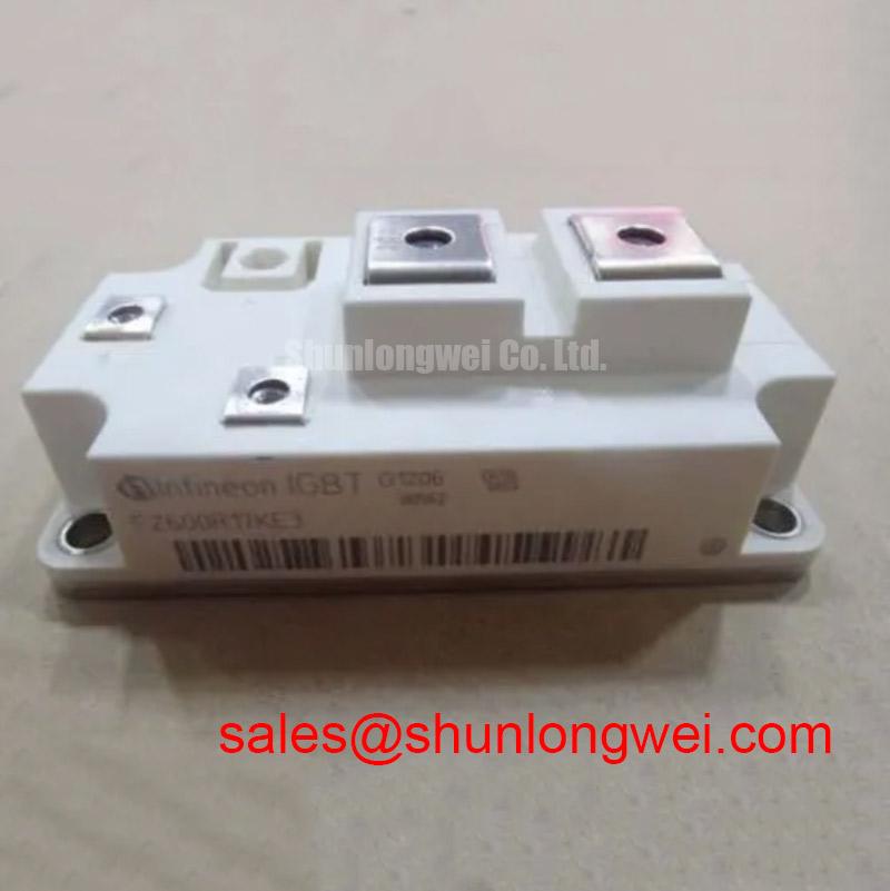
The FZ600R17KE3 represents a highly reliable technical choice for power electronics designers focusing on the power semiconductors market. By utilizing its 10 $mu s$ short-circuit withstand time and low conduction losses, engineers can build resilient energy conversion systems that meet the rigorous standards of modern industry.