FF300R12KE3 IGBT Module: A Technical Review for High-Efficiency Power Conversion
FF300R12KE3 IGBT Module: A Technical Analysis
Low-Loss Power Switching with TRENCHSTOP™ IGBT3 Technology
The Infineon FF300R12KE3 is a 1200V, 300A dual IGBT module engineered for high-efficiency power conversion. This module integrates Infineon’s TRENCHSTOP™ IGBT3 and Emitter Controlled diode technology, establishing a benchmark for low conduction and switching losses in demanding applications. Its robust EconoPACK™ 3 package ensures reliable thermal performance, enabling engineers to develop more compact and efficient power systems. This technical composition allows for effective management of power dissipation, a critical factor when calculating thermal resistance for heatsink selection.
- Core Specifications: 1200V | 300A (ICnom) | VCE(sat) 1.70V (typ.)
- Key Advantages: Reduced conduction losses, high switching frequency capability.
Download the Official FF300R12KE3 Datasheet (PDF)

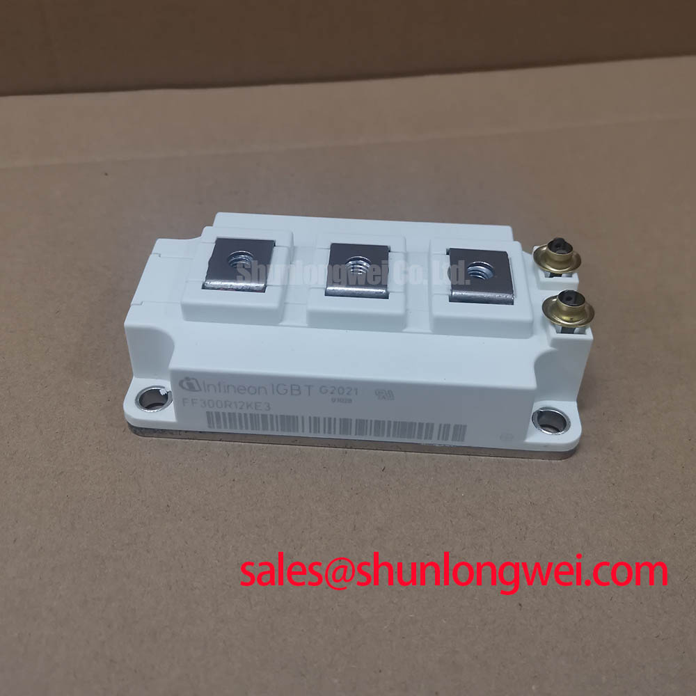
Technical Analysis: Efficiency and Thermal Management
A defining characteristic of the FF300R12KE3 is its low collector-emitter saturation voltage (VCE(sat)). The datasheet specifies a typical VCE(sat) of just 1.70V at the nominal current of 300A and a junction temperature of 25°C. This parameter is critical as it directly dictates the amount of power dissipated as heat during the transistor’s on-state. A lower VCE(sat) translates to higher converter efficiency and reduced requirements for thermal management hardware, a core topic explored in our guide to IGBT thermal design.
The module’s thermal resistance from junction to case (RthJC) is another pivotal parameter for system reliability. For the IGBT, this is specified at 0.085 K/W. Think of thermal resistance as the width of a pipe for heat; a lower value indicates a wider pipe, allowing heat to escape more easily from the active semiconductor junction to the heatsink. This efficient heat extraction is fundamental to maintaining the junction temperature within the specified maximum operating limit of 150°C, ensuring long-term operational stability.
Optimized Application Scenarios
The electrical and thermal characteristics of the FF300R12KE3 make it highly suitable for a range of power conversion applications:
- Motor Drives: The module’s low switching losses and robust half-bridge configuration are ideal for creating efficient and precise variable frequency drives (VFDs).
- Solar Inverters: High efficiency is paramount in renewable energy. The low VCE(sat) directly contributes to maximizing the energy harvested from photovoltaic arrays.
- Uninterruptible Power Supplies (UPS): The module’s ability to handle a repetitive peak collector current of 600A ensures reliability during load transients and fault conditions.
- Welding Equipment: The robust thermal performance and high current capability are well-suited for the demanding pulsed power requirements of modern welding power supplies.
The combination of low losses and superior thermal transfer makes this module a best-fit for power densities where performance cannot be compromised.
Key Specification Parameters for FF300R12KE3
| IGBT, Inverter – Maximum Ratings | ||
|---|---|---|
| Collector-Emitter Voltage (VCES) | 1200 V | |
| Continuous DC Collector Current (IC) | 440 A (TC = 25°C) | |
| Nominal Collector Current (ICnom) | 300 A | |
| Repetitive Peak Collector Current (ICRM) | 600 A (tP = 1 ms) | |
| Total Power Dissipation (Ptot) | 1450 W (TC = 25°C) | |
| IGBT, Inverter – Characteristic Values | ||
| Collector-Emitter Saturation Voltage (VCEsat) | 1.70 V (typ.) at IC = 300A, VGE = 15V | |
| Gate Threshold Voltage (VGE(th)) | 5.0 V to 6.5 V | |
| Thermal Resistance, Junction to Case (RthJC) | 0.085 K/W per IGBT | |
Engineer’s Frequently Asked Questions
1. What is the recommended mounting torque for the FF300R12KE3?
The datasheet specifies a mounting torque of 3.0 – 6.0 Nm for the module’s M6 mounting screws. Adhering to this torque specification is crucial for establishing a low-resistance thermal path to the heatsink.
2. How can I accurately estimate power losses for this module in my design?
Total power loss is the sum of conduction and switching losses. Conduction loss can be calculated using the VCE(sat) and IC values from the datasheet’s characteristic curves. Switching losses (Eon and Eoff) are also provided and depend on the DC-link voltage, current, and gate resistor value. Infineon often provides online simulation tools for more precise calculations.
3. Is an integrated NTC thermistor included for temperature monitoring?
Yes, the FF300R12KE3 includes an NTC thermistor. Its resistance characteristics are detailed in the datasheet, allowing for direct monitoring of the module’s baseplate temperature, a key feature for implementing over-temperature protection.
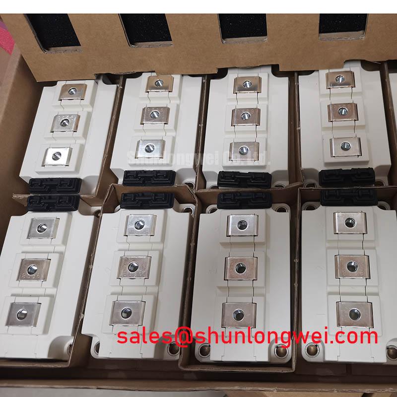
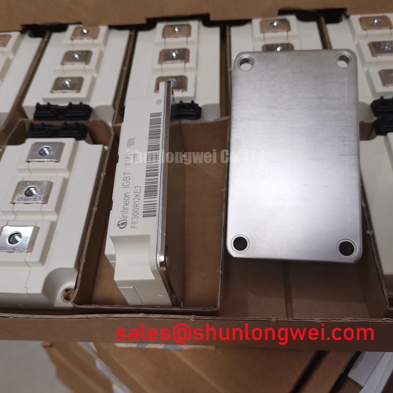
Enabling Efficient and Reliable Power Systems
The FF300R12KE3 module provides a well-documented, high-performance solution for power conversion systems. Its foundation on TRENCHSTOP™ IGBT3 technology delivers a compelling balance of low on-state voltage and minimal switching energy. This combination allows design engineers to achieve higher efficiency, increase power density, and ensure the thermal stability required for long-term system reliability.