FF450R12KT4 IGBT Module: A Technical Analysis for High-Power Systems
FF450R12KT4: 1200V IGBT for High-Efficiency Power Systems
Technical Analysis of the FF450R12KT4 IGBT Module
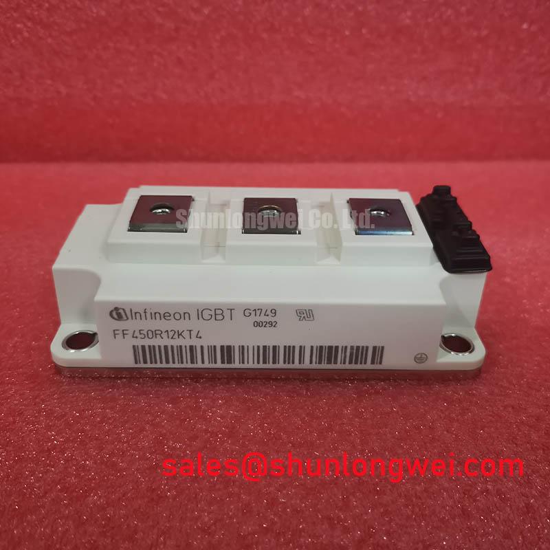
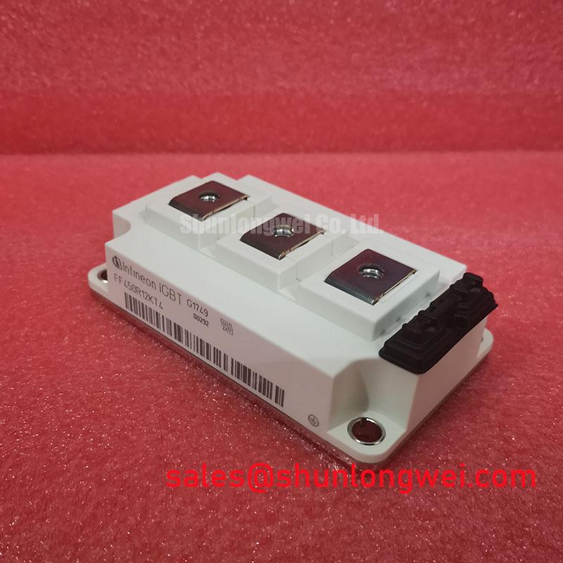
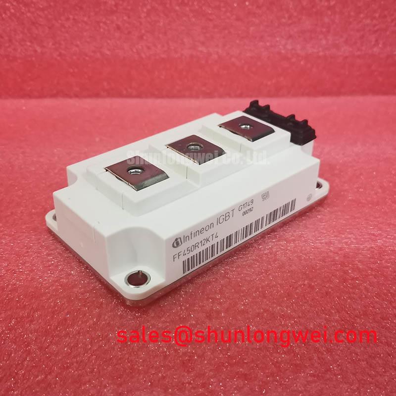
The Infineon FF450R12KT4 is a 1200V, 450A dual IGBT module engineered for high-reliability power conversion systems. This module leverages Infineon’s TRENCHSTOP™ IGBT4 technology, delivering a balanced profile of low conduction and switching losses, a key consideration for system efficiency. Housed in the industry-standard EconoDUAL™ 3 package, it provides a robust and thermally efficient solution for demanding industrial environments.
- Core Specifications: 1200V | 450A | VCE(sat) (typ.) 1.75V
- Key Advantages: Balanced loss profile for medium switching frequencies, high thermal cycling capability.
This module is well-suited for applications where operational reliability and efficiency are critical. Its positive temperature coefficient of the saturation voltage simplifies the process of paralleling multiple IGBT modules for higher power output.
Download The Official FF450R12KT4 Datasheet (PDF)
A Deeper Look at IGBT4 Technology and Thermal Performance
The core of the FF450R12KT4 is its TRENCHSTOP™ IGBT4 silicon. This technology provides a low collector-emitter saturation voltage (VCE(sat)) of 1.75V (typical at 25°C), which directly reduces conduction losses—a significant factor in applications with long on-state durations, such as motor drives. This parameter is analogous to the resistance of a pipe; a lower VCE(sat) value means less opposition to current flow, generating less heat and improving overall energy efficiency.
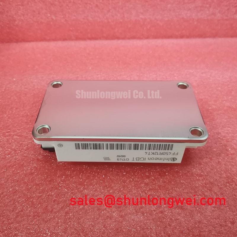
The module’s thermal design is critical for long-term reliability. Its junction-to-case thermal resistance (Rth(j-c)) is specified at a maximum of 0.055 K/W for each IGBT. This low thermal resistance, facilitated by an isolated aluminum baseplate and Al2O3 substrate, ensures efficient heat transfer from the silicon die to the heatsink. Effective thermal management is crucial for preventing overheating, which is a common cause of IGBT failures.
Optimized Application Scenarios
The specific characteristics of the FF450R12KT4 make it an excellent component for several high-power applications:
- Variable Frequency Drives (VFDs): The module’s robustness and low conduction losses are ideal for controlling industrial motors, where it can efficiently manage high-torque and variable loads.
- Central Solar Inverters: High efficiency is paramount for maximizing energy harvest. The low VCE(sat) of this module directly translates to reduced power loss during the inversion process.
- Uninterruptible Power Supplies (UPS): For critical systems, the module’s proven reliability and stable thermal performance ensure the UPS can handle load demands and deliver clean power without interruption.
- High-Power Converters: The 1200V blocking voltage provides a substantial safety margin for converters connected to industrial power grids.
This module is a best-in-class fit for medium-frequency power conversion systems requiring a balance between performance, efficiency, and long-term operational reliability.
Key Specifications of the FF450R12KT4
| Parameter | Value | Conditions |
|---|---|---|
| Collector-Emitter Voltage (VCES) | 1200 V | Tvj = 25°C |
| Nominal Collector Current (IC nom) | 450 A | TC = 100°C |
| Collector-Emitter Saturation Voltage (VCE(sat)) | 1.75 V (typ) | IC = 450 A, VGE = 15 V, Tvj = 25°C |
| Gate Threshold Voltage (VGE(th)) | 5.2V – 6.4V | IC = 17.0 mA, Tvj = 25°C |
| Total Power Dissipation (Ptot) | 2400 W | TC = 25°C |
| Operating Junction Temperature (Tvj op) | -40°C to +150°C | |
| Package | EconoDUAL™ 3 | 62mm module |
Note: All specifications are sourced directly from the official manufacturer’s datasheet.
Engineer’s FAQ
1. What is the recommended heatsink thermal resistance for this module?
To determine the required heatsink thermal resistance (Rth(h-a)), you must first calculate the total power loss (Ptot) under your specific operating conditions (current, voltage, switching frequency). Then, use the formula: Rth(h-a) = (Tj – Ta) / Ptot – Rth(j-c) – Rth(c-h), ensuring the junction temperature (Tj) stays within the 150°C maximum operating limit.
2. How does the positive temperature coefficient of VCE(sat) help in paralleling?
The positive temperature coefficient means that as an IGBT heats up, its on-state voltage increases slightly. In a parallel configuration, if one module carries more current and gets hotter, its VCE(sat) will rise. This rise in “resistance” naturally diverts current to the cooler modules, creating a self-balancing effect that prevents thermal runaway. For a deeper understanding, explore our guide on the architecture of modern power switching.
3. What are the best practices for mounting this module?
Ensure a flat and clean mounting surface to achieve a low thermal resistance case-to-heatsink (Rth(c-h)). Apply a thin, uniform layer of thermal interface material. Use the specified torque settings for the power and auxiliary terminals to ensure a secure connection without inducing mechanical stress on the module’s housing or internal structure.
Enabling Robust Power Conversion
The FF450R12KT4 provides a foundation for creating reliable and efficient high-power inverters and converters. Its use of proven TRENCHSTOP™ IGBT4 technology within the industry-standard EconoDUAL™ 3 package offers a solution that balances performance, thermal stability, and long-term operational life, enabling engineers to meet demanding system requirements.