FS6R06VE3_B2 6A/600V SPM Module: An Integrated Solution for Compact Motor Drives
FS6R0นานาVE3_B2 600V 6A SPM® 27-II IGBT Module
Introduction and Core Highlights
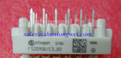
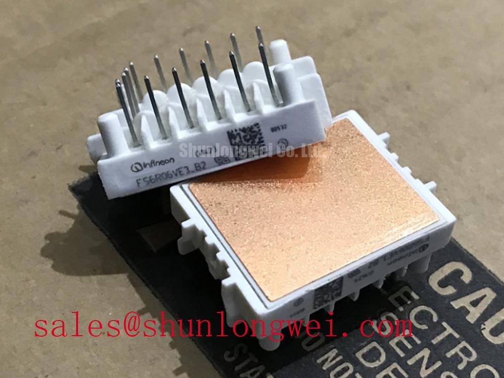
The FS6R06VE3_B2 is a highly integrated SPM® 27-II module from Infineon Technologies, engineered to provide a compact and efficient power stage for low-power motor drive applications. This module’s primary value is its functional integration, which combines a three-phase inverter with built-in gate drivers and protection features, significantly reducing system complexity and accelerating development time. It offers a robust solution for controlling variable speed drives in a small footprint.
- Core Specifications: 600V | 6A | VCE(sat) (typ.) 1.55V
- Key Advantages: Simplifies PCB layout with an integrated HVIC gate driver; enhances system reliability with a built-in NTC thermistor for temperature monitoring.
- Design Consideration: For systems requiring precise thermal management, the integrated NTC thermistor provides a direct and accurate method for monitoring the module’s operating temperature.
Download Official Datasheet (PDF)
Technical Analysis of Integrated Features
The engineering value of the FS6R06VE3_B2 lies in its intelligent integration. The built-in High-Voltage IC (HVIC) serves as the control center for the IGBTs, translating low-voltage logic signals from a microcontroller into the high-current gate drive required for switching. This eliminates the need for external optocouplers and isolated power supplies for the high-side drivers, directly contributing to a smaller bill of materials (BOM) and a more compact PCB design. The module also incorporates under-voltage lock-out (UVLO) protection, which safeguards the IGBTs from operating with insufficient gate voltage, a common cause of failure.
Effective thermal management is crucial for power module longevity. This module addresses this by embedding a Negative Temperature Coefficient (NTC) thermistor. This integrated sensor acts like a dedicated thermometer for the module’s substrate. Its resistance changes predictably with temperature, providing a reliable feedback signal to the system’s controller. This allows for the implementation of over-temperature protection, which can scale back power or shut down the system before thermal damage occurs, significantly enhancing the operational robustness of the end application.
Optimized Application Scenarios
The FS6R06VE3_B2 is specified for applications that demand high efficiency and a compact power stage. Its characteristics make it particularly suitable for:
- Home Appliance Motor Drives: In devices like washing machines and air conditioners, the module’s high level of integration and reliability are ideal for space-constrained and cost-sensitive designs.
- Small Industrial Fans and Pumps: The 6A continuous current rating is well-suited for low-power industrial motors, where the module’s built-in protection features enhance operational safety.
- Robotics and Automation: For servo and stepper motor controls, the simplified gate drive and compact footprint allow for denser, more efficient system designs.
This module is best matched for variable frequency drive applications under 1.5 kW requiring a streamlined design cycle and high operational reliability.
Key Specifications of FS6R06VE3_B2
| Absolute Maximum Ratings (TC = 25°C unless otherwise noted) | ||
|---|---|---|
| Parameter | Symbol | Value |
| Collector-Emitter Voltage | VCES | 600 V |
| Continuous DC Collector Current @ TC=80°C | IC nom | 6 A |
| Total Power Dissipation | Ptot | 20 W |
| Electrical Characteristics (Tvj = 25°C) | ||
| Collector-Emitter Saturation Voltage (IC = 6A, VGE = 15V) | VCEsat | 1.55 V (typ.), 1.70 V (max.) |
| NTC Resistance | R25 | 5.00 kΩ (typ.) |
| Isolation Voltage (AC, 1 min) | VISOL | 2000 VRMS |
Engineer’s FAQ
- How should the integrated NTC thermistor be used for thermal protection?
- The NTC thermistor provides a resistance value that corresponds to the module’s temperature. This should be connected to a voltage divider circuit, with the output read by a microcontroller’s ADC. The microcontroller can then use a look-up table or the B-value equation provided in the datasheet to calculate the real-time temperature and trigger a fault condition if it exceeds the safe operating limit.
- What are the primary mounting and layout considerations for this module?
- A low-inductance PCB layout is essential for optimal switching performance. Keep the traces between the module’s control pins and the microcontroller as short as possible. Ensure proper thermal contact by applying a uniform layer of thermal grease between the module’s baseplate and the heatsink. The heatsink must be properly sized to dissipate the module’s power losses under worst-case operating conditions.
- What is the function of the bootstrap circuit for the high-side gate driver?
- The bootstrap circuit uses an external capacitor and diode (often integrated) to create a floating power supply for each high-side gate driver. When the low-side IGBT is on, the capacitor charges from the control supply. When the high-side IGBT needs to turn on, this charged capacitor provides the necessary gate voltage relative to the high-side emitter, which is switching at high voltage.
Enabling Efficient Power Conversion
The FS6R06VE3_B2 offers a compelling solution for engineers tasked with developing compact and reliable motor drives. By integrating the core components of a power inverter stage into a single, thermally efficient package, it streamlines the design process and enhances system-level robustness. This module empowers the creation of efficient power conversion systems for a wide range of applications.