Infineon FF900R17ME7_B11 1700V 900A Dual IGBT Module Technical Overview
FF900R17ME7_B11 Infineon 1700V 900A Dual IGBT Module
Introduction and Core Product Specifications
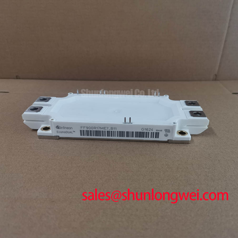
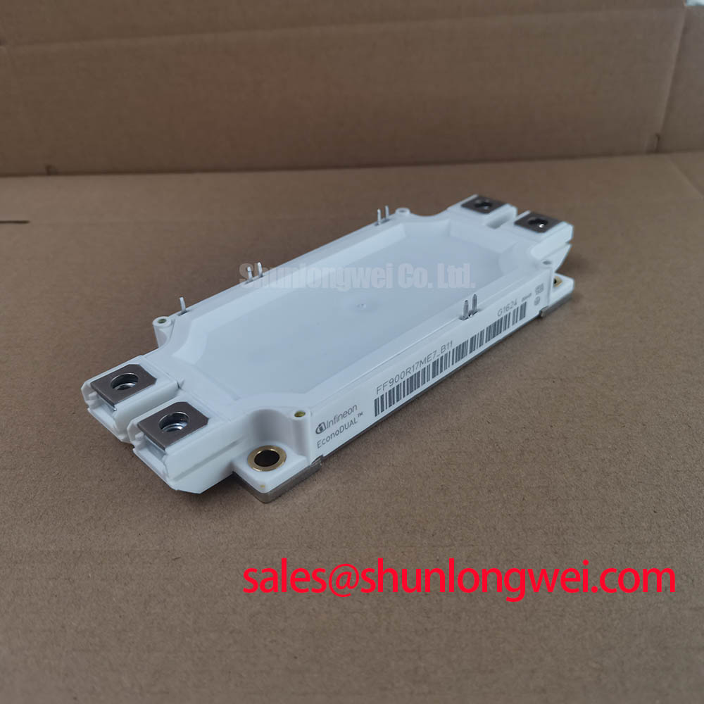
The FF900R17ME7_B11 is a dual-switch IGBT Module housed in the industry-standard EconoDUAL™ 3 package. It implements the advanced Infineon TRENCHSTOP™ IGBT7 technology, providing high power density with minimized switching losses. How can power designers increase system throughput without changing mechanical dimensions? This module addresses that constraint by packing a nominal 900A capacity into the classic EconoDUAL™ 3 package.
- Core Parameters: 1700V | 900A | VCE(sat) 1.70V (Typical)
- Integrated Sensors: Built-in negative temperature coefficient (NTC) thermistor
- Engineering Values: Reduced conduction losses and simplified gate driver complexity
Download Official Datasheet (PDF)
Technical Analysis and Engineering Design Values
The electrical performance of the FF900R17ME7_B11 is optimized through its trench gate and emitter structure. This 7th generation technology reduces conduction losses by allowing a lower collector-emitter saturation voltage compared to previous generations. By maintaining a typical VCE(sat) of 1.70V at its rated 900A current, the system exhibits lower static losses. This loss reduction is highly beneficial during continuous, high-current operations.
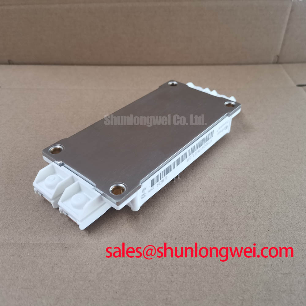
Let us look at thermal path limits. You can think of the transient thermal impedance of the module as a narrow water pipe. A narrower pipe limits flow, causing water to build up. Similarly, high thermal resistance blocks heat dissipation, raising the junction temperature. This module leverages optimized substrate materials to widen that thermal path. The result is a high continuous junction temperature limit of 175°C under overload conditions.
Additionally, managing electromagnetic interference is simplified. The controlled switching speed (dv/dt) prevents rapid voltage transitions that generate high-frequency electrical noise. This balanced electrical performance helps minimize stress on system-level components. It also protects the structural integrity of the module’s internal isolation. For broader power semiconductor options, engineers can explore the power semiconductors selection.

Optimized Application Scenarios
- Wind Turbine Inverters: The 1700V rating offers the voltage margin required to handle grid fluctuations. The high power cycling capability supports variable wind speeds.
- Solar Power Converters: Low conduction losses maximize overall energy harvesting efficiency. This is crucial for utility-scale PV plants.
- Industrial Motor Drives: High overcurrent tolerance handles heavy startup loads in high-torque industrial machinery.
- Uninterruptible Power Supplies (UPS): Fast switching speeds and low loss profiles enable compact filter designs.
Best-Fit Conclusion: The module is best suited for high-power industrial converters requiring maximum current capacity within a standardized EconoDUAL™ 3 footprint.
Key Technical Specifications
| Parameter | Value / Specification | Conditions / Notes |
|---|---|---|
| Collector-Emitter Voltage (VCES) | 1700 V | Tvj = 25°C |
| Continuous DC Collector Current (IC) | 900 A | TC = 100°C, Tvj_max = 175°C |
| Repetitive Peak Collector Current (ICRM) | 1800 A | tp = 1 ms |
| IGBT typical VCE(sat) | 1.70 V | IC = 900 A, VGE = 15 V, Tvj = 25°C |
| Gate-Emitter Peak Voltage (VGES) | +/- 20 V | Absolute maximum rating |
| Integrated NTC Resistance | 5 kΩ | TNTC = 25°C, typical |
| Isolation Test Voltage (VISOL) | 3.4 kV | RMS, f = 50 Hz, t = 1 min |
Engineering FAQ
How does the integrated NTC thermistor assist in protection?
The module includes an internal NTC sensor that monitors the baseplate temperature in real-time. This helps prevent thermal runaway. To understand thermal safety architectures better, see the guide on integrated NTC protection.
What are the primary factors affecting switching losses in high-frequency applications?
Switching losses are highly dependent on stray inductance and gate resistance (Rg). To mitigate voltage overshoot risks during high-frequency operation, read our analysis on parasitic inductance in IGBT switching.
What type of environmental protection does the housing fill provide?
The internal components are embedded in high-grade silicone gel. This gel provides dielectric insulation and buffers thermomechanical stress. For material details, see the study on silicone gel insulation.
Factual Performance Summary
The FF900R17ME7_B11 represents a significant step forward in power density. By integrating 1700V breakdown capabilities and 900A handling in a standardized footprint, it allows engineers to optimize inverter efficiency. The advanced IGBT7 technology ensures your power designs achieve high thermal performance and reliable conduction efficiency.