Fuji 2MBI150UM-120-50 1200V 150A Dual IGBT Module: Technical Overview and Applications
Fuji 2MBI150UM-120-50 1200V 150A Dual IGBT Power Module
Product Overview and Engineering Highlights
The 2MBI150UM-120-50 is a high-performance 1200V, 150A dual IGBT module designed by Fuji Electric for power conversion applications. Utilizing advanced trench-gate field-stop technology, this module balances low conduction losses with optimized switching behavior. It serves as a core switching element in half-bridge converter topologies across power semiconductor systems.
- Core Parameters: 1200V Collector-Emitter Voltage ($V_{CES}$), 150A Continuous Collector Current ($I_C$ at $T_C=80^circtext{C}$), 300A Pulse Collector Current ($I_{CP}$).
- Key Benefits: Reduced conduction losses via optimized collector-emitter saturation voltage ($V_{CE(sat)}$) and simplified thermal management with an electrically insulated mounting structure.
- Design Solution: Addresses high thermal stress and switching loss requirements in industrial motor drives and power supplies.
Download Official Fuji Electric Datasheet Reference


Technical Analysis Around Conduction Efficiency
The 2MBI150UM-120-50 features a dual (half-bridge) circuit topology in a standardized industrial package. Its internal structure combines trench-gate IGBT chips with fast-recovery free-wheeling diodes (FWD). This combination minimizes the forward collector-emitter saturation voltage, directly lowering $I^2R$ power dissipation during steady-state operation. Engineers can review how lower VCE(sat) trench gate architecture reduces overall thermal burden in continuously loaded converters.
Thermal management relies on internal Direct Copper Bonding (DCB) substrates. Consider thermal resistance like the physical diameter of a water drain pipe: a lower thermal resistance value allows generated heat to flow away effortlessly into the heatsink. This keeps internal silicon junction temperatures well within safe limits under high current demands. Using isolated baseplates simplifies mounting while ensuring electrical isolation between the power circuit and cooling chassis.
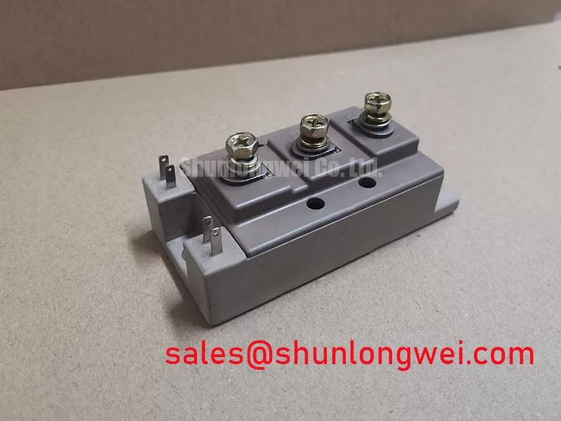
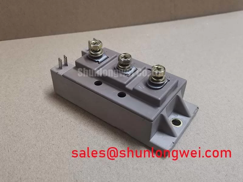

The module is designed to control voltage overshoot caused by high-speed switching transitions. Minimizing internal stray inductance reduces voltage spikes across the collector and emitter terminals. Designers looking to optimize gate drive circuits can explore strategies to control parasitic inductance during high-frequency switching.
Target Industrial Applications
- Variable Frequency Drives (VFDs): Serves as the primary inverter stage for controlling 380V to 480V three-phase AC motors in industrial automation.
- Uninterruptible Power Supplies (UPS): Delivers reliable DC-to-AC conversion in high-capacity backup power units.
- Industrial Welding Power Supplies: Handles fast pulse switching duty cycles under heavy current loads.
- Solar Inverters: Converts DC string energy to grid-compliant AC power with minimized thermal loss.
Application Suitability Statement: The 2MBI150UM-120-50 provides an optimal match for 1200V half-bridge topologies requiring continuous collector currents up to 150A at $80^circtext{C}$.
Key Specifications Table
| Absolute Maximum Ratings ($T_j = 25^circtext{C}$ unless specified) | ||
|---|---|---|
| Collector-Emitter Voltage | $V_{CES}$ | 1200 V |
| Gate-Emitter Voltage | $V_{GES}$ | $pm 20$ V |
| Continuous Collector Current | $I_C$ ($T_C = 80^circtext{C}$) | 150 A |
| Pulsed Collector Current | $I_{CP}$ ($1text{ ms}$) | 300 A |
| Maximum Power Dissipation | $P_D$ (Per IGBT) | 780 W (approx.) |
| Operating Junction Temperature | $T_j$ | -40 to +150 $circtext{C}$ |
| Electrical and Thermal Characteristics | ||
| Collector Cut-off Current | $I_{CES}$ ($V_{CE} = 1200text{V}$) | 1.0 mA (Max) |
| Gate-Emitter Threshold Voltage | $V_{GE(th)}$ ($V_{CE} = 20text{V}, I_C = 150text{mA}$) | 6.0 to 7.5 V |
| Collector-Emitter Saturation Voltage | $V_{CE(sat)}$ ($I_C = 150text{A}, V_{GE} = 15text{V}$) | 1.75 V (Typical) |
| Thermal Resistance (Junction-to-Case) | $R_{th(j-c)}$ (Per IGBT) | 0.16 $^circtext{C}/text{W}$ (Max) |
| Isolation Voltage | $V_{iso}$ (AC 1 min) | 2500 V |
Engineering FAQ
What is the recommended gate driver voltage for the 2MBI150UM-120-50?
The standard gate-drive supply voltage is $+15text{V}$ for turn-on. A negative bias (such as $-5text{V}$ to $-15text{V}$) is recommended during turn-off to prevent accidental dv/dt-induced turn-on caused by Miller capacitance in noisy industrial environments.
How should thermal compound be applied when mounting this module?
Apply a uniform layer of thermal grease (30 to 50 microns thickness) to the module’s bottom baseplate. Tighten the mounting screws to the specified torque rating found in the datasheet to ensure uniform pressure and low thermal contact resistance.
Can this module be used in a full-bridge inverter configuration?
Yes. Two 2MBI150UM-120-50 half-bridge modules can be paired to form a single-phase full-bridge inverter, or three modules can be used to construct a full three-phase AC inverter bridge.
Summary
The Fuji 2MBI150UM-120-50 IGBT module delivers a robust combination of 1200V blocking voltage, 150A continuous current rating, and low conduction dissipation. Its proven half-bridge package enables power electronics engineers to construct reliable, efficient power conversion equipment for demanding industrial environments.