Fuji 2MBI300VH-120-50 V-Series IGBT Module: A Technical Review
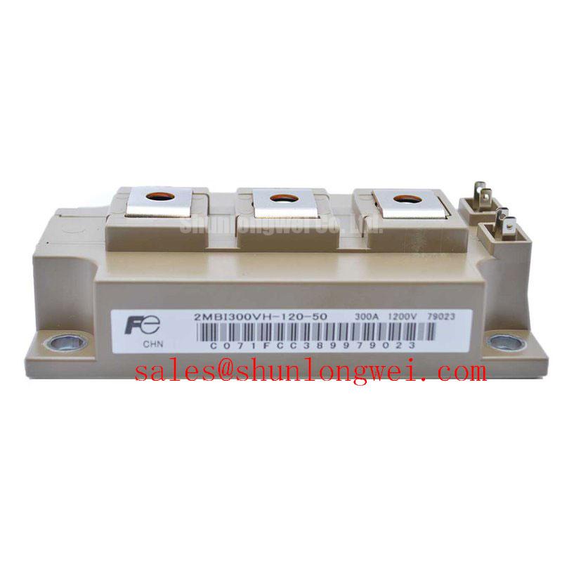
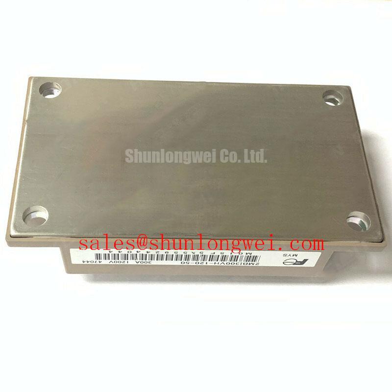
Fuji 2MBI300VH-120-50 1200V 300A V-Series IGBT Module
Introduction to the 2MBI300VH-120-50 for High-Frequency Power Conversion
The Fuji Electric 2MBI300VH-120-50 is a dual IGBT module from the 6th Generation V-Series, engineered for high-frequency power conversion systems. It integrates two IGBTs in a half-bridge configuration, delivering a robust solution that balances low conduction and switching losses. This performance is achieved through advanced trench gate and thin-wafer technologies, making it a strong candidate for designs where thermal efficiency and power density are critical objectives. By enabling higher switching frequencies, this module allows for the use of smaller passive components, directly supporting system miniaturization.
- Core Specifications: 1200V | 300A | VCE(sat) 2.30V (typ)
- Key Advantages: Low thermal resistance for improved heat dissipation; Optimized for fast switching to enhance system power density.
Download Official Datasheet (PDF)
Technical Analysis
The 2MBI300VH-120-50’s performance is rooted in its V-Series chipset. This design provides a typical Collector-Emitter Saturation Voltage (VCE(sat)) of 2.30V at its nominal 300A current and a junction temperature of 150°C. This parameter is crucial as it directly dictates conduction losses. Think of VCE(sat) as the resistance of a fully open water valve; a lower value means less restriction, resulting in less energy wasted as heat. This efficiency is a direct result of Fuji’s trench-gate structure, which enables lower on-state voltage compared to older planar technologies.
In addition to low conduction losses, the module is optimized for dynamic performance. With typical turn-on (ton) and turn-off (toff) times of 0.60 µs and 0.80 µs respectively at 150°C, it supports the high switching frequencies required in modern inverters and servo drives. Faster switching allows engineers to specify smaller, lighter, and often less expensive magnetic components, thereby increasing the overall power density and reducing the system’s physical footprint. The module’s low-inductance package design further supports this, minimizing voltage overshoot during fast switching events.
System reliability is underpinned by effective thermal management. The 2MBI300VH-120-50 specifies a low thermal resistance from junction to case (Rth(j-c)) of 0.093 °C/W for the IGBT. This value acts like the width of a pipe for heat dissipation; a lower thermal resistance provides a wider path for heat to escape from the silicon chip to the heatsink. This efficient heat transfer, combined with a maximum junction temperature of 175°C, provides a substantial thermal margin for robust operation under demanding industrial conditions. For a deeper understanding, explore this guide on mastering IGBT thermal design.
Optimized Application Scenarios
- High-Frequency Motor Drives: The module’s fast switching capabilities permit higher PWM frequencies. This results in smoother motor torque, reduced audible noise, and higher precision, which is essential for AC and DC servo drive amplifiers.
- Uninterruptible Power Supplies (UPS): In UPS systems, efficiency and reliability are paramount. The low VCE(sat) minimizes power loss during conversion, while the robust thermal design and 175°C maximum junction temperature ensure dependable operation during critical backup events.
- Solar and Wind Power Inverters: The balance of low switching and conduction losses helps maximize the energy harvested and delivered to the grid. The 1200V rating provides the necessary voltage headroom for inverters connected to high-voltage DC arrays.
Its balanced V-series features make it an excellent fit for high-frequency converters where efficiency and compact design are key engineering goals.
Key Specifications of the 2MBI300VH-120-50
| Parameter | Value | |
|---|---|---|
| Absolute Maximum Ratings | ||
| Collector-Emitter Voltage (VCES) | 1200 V | |
| Continuous Collector Current (IC) | Tc=100°C | 300 A |
| Maximum Junction Temperature (Tj max) | 175 °C | |
| Electrical Characteristics (IGBT) | ||
| Collector-Emitter Saturation Voltage (VCE(sat)) | IC=300A, VGE=15V, Tj=150°C | 2.30 V (typ) |
| Gate-Emitter Threshold Voltage (VGE(th)) | IC=300mA, VCE=20V | 6.0V to 7.0V |
| Turn-on Time (ton) | Tj=150°C, RG=1.8Ω | 0.60 µs (typ) |
| Turn-off Time (toff) | Tj=150°C, RG=1.8Ω | 0.80 µs (typ) |
| Thermal Characteristics | ||
| Thermal Resistance, Junction-to-Case (Rth(j-c)) | IGBT | 0.093 °C/W (max) |
| Thermal Resistance, Junction-to-Case (Rth(j-c)) | FWD | 0.150 °C/W (max) |
For a deeper look into the components that define system performance, see this article on the critical role of the free-wheeling diode.
Engineer’s FAQ
- What are the recommended gate driver settings for the 2MBI300VH-120-50?
- The datasheet specifies test conditions using a gate voltage (VGE) of ±15V. A starting external gate resistor (RG) of 1.8Ω is used for characterizing the switching times. This value should be optimized based on the specific application’s requirements for balancing switching speed, EMI, and voltage overshoot. For further reading, consult resources on robust gate drive design.
- How does the module’s thermal resistance impact heatsink selection?
- The maximum IGBT thermal resistance (Rth(j-c)) of 0.093 °C/W is a critical value for thermal calculations. It allows engineers to accurately calculate the temperature rise from the IGBT junction to the module case. This data, combined with the total estimated power loss and the contact thermal resistance (Rth(c-f)), is essential for selecting a heatsink that can maintain the junction temperature below the maximum operating limit of 150°C.
- Can the 2MBI300VH-120-50 be operated in parallel?
- Yes, paralleling is possible. The datasheet shows that VCE(sat) has a positive temperature coefficient, which aids in balancing current between parallel modules. However, successful paralleling requires careful attention to symmetrical layout design to equalize stray inductances and ensure uniform current distribution, especially during switching. Detailed guidance can be found in specialized application notes like Infineon’s on paralleling IGBT modules.
- What is the significance of the 175°C maximum junction temperature?
- The 175°C maximum junction temperature (Tj max) represents the device’s short-term survival limit. While the recommended maximum operating temperature (Tjop) is 150°C for continuous operation, the higher Tj max provides a safety margin. This enhances the module’s robustness against unexpected load transients and short-term overpower conditions, contributing to overall system reliability.
Concluding Statement
The 2MBI300VH-120-50 provides system designers with a well-documented and robust component for building efficient and reliable power converters. Its foundation in Fuji Electric’s V-Series technology offers a proven path to achieving demanding performance targets in a standard industrial package.