Fuji 2MBI50N-120 IGBT Module: A Technical Analysis for Industrial Applications
2MBI5O-120 IGBT Module | 1200V 50A Dual Module
Technical Analysis of the Fuji Electric 2MBI50N-120 IGBT Module
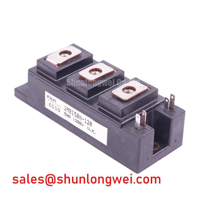
This Fuji Electric 2MBI50N-120 is a dual IGBT module providing a robust 1200V, 50A half-bridge configuration for industrial power conversion systems. Its design centers on delivering a balanced performance profile, leveraging Non-Punch Through (NPT) IGBT technology to ensure operational stability and reliability in demanding applications. This module is engineered for systems where durable, predictable performance is a primary design criterion.
- Core Specifications: 1200V | 50A | VCE(sat) 2.7V (Max)
- Key Advantages: Square RBSOA for enhanced ruggedness, low overall power dissipation.
- Primary Function: Serves as a reliable switching element in high-power inverters and motor drives.
Download the 2MBI50N-120 Datasheet (PDF)
A Deeper Look at the 2MBI50N-120’s Engineering Attributes
The technical specifications of the 2MBI50N-120 reflect a focus on system reliability and thermal efficiency. Two parameters are particularly indicative of its intended operational environment: the collector-emitter saturation voltage and the thermal resistance characteristics. These figures are critical for engineers performing thermal modeling and projecting long-term system performance.
Collector-Emitter Saturation Voltage (VCE(sat))
The 2MBI50N-120 specifies a maximum VCE(sat) of 2.7V at a junction temperature of 125°C. This voltage represents the residual drop across the IGBT when it is fully “on,” directly contributing to conduction losses. Think of VCE(sat) as a form of electrical friction; a lower value translates to less energy wasted as heat during operation. For a 50A load, this parameter is a primary factor in the total power dissipation, influencing the required capacity of the system’s thermal management solution. A well-managed thermal environment is essential for maintaining the module within its Safe Operating Area (SOA).

Thermal Resistance and Heatsink Calculation
The module’s thermal resistance from junction to case (Rth(j-c)) for the IGBT is documented at 0.32°C/W. This value is analogous to the width of a pipe for heat flow; a lower thermal resistance allows heat to escape the semiconductor junction more easily. Engineers use this specification as a fundamental input for calculating the required performance of an external heatsink. An accurate calculation ensures the IGBT’s junction temperature remains below the maximum rating of 150°C under worst-case load conditions, a key aspect of reliable power system design.
Optimized Application Scenarios
The balanced electrical characteristics and robust thermal design of the 2MBI50N-120 make it a suitable component for a range of industrial applications:
- AC Motor Controls: Its 1200V rating and 50A current capability are well-matched for variable frequency drives (VFDs) controlling industrial motors in pumps, fans, and conveyors.
- Uninterruptible Power Supplies (UPS): The module’s reliability and defined SOA provide the stability needed for critical backup power systems where uptime is non-negotiable.
- Welding Power Supplies: The robust design, including a square Reverse Bias Safe Operating Area (RBSOA), allows the module to withstand the demanding, high-current pulse conditions found in welding applications.
- High-Power Switching Applications: The module serves as a dependable building block for various general-purpose inverters and power conversion systems.
This module’s specifications make it a strong candidate for power systems requiring proven reliability and a straightforward implementation path over ultra-high switching frequencies.
Key Specifications of the 2MBI50N-120
| Absolute Maximum Ratings (Tc=25°C) | ||
|---|---|---|
| Parameter | Symbol | Value |
| Collector-Emitter Voltage | VCES | 1200V |
| Gate-Emitter Voltage | VGES | ±20V |
| Continuous Collector Current (Tc=80°C) | IC | 50A |
| Continuous Forward Current (Diode, Tc=80°C) | IF | 50A |
| Total Power Dissipation (Per IGBT) | PC | 390W |
| Operating Junction Temperature | Tj | -40 to +150°C |
| Electrical and Thermal Characteristics (Tj=125°C unless otherwise specified) | ||
| Collector-Emitter Saturation Voltage (IC=50A, VGE=15V) | VCE(sat) | 2.7V (Max) |
| Forward Voltage (Diode, IF=50A) | VF | 2.6V (Max) |
| Thermal Resistance (Junction to Case, IGBT) | Rth(j-c) | 0.32°C/W (Max) |
| Thermal Resistance (Junction to Case, Diode) | Rth(j-c) | 0.63°C/W (Max) |
Note: The parameters listed above are for reference. For complete and verified technical data, consult the official manufacturer’s datasheet.
Engineer’s Frequently Asked Questions
1. What is the recommended mounting torque for the 2MBI50N-120’s terminals and mounting screws?
According to the datasheet, the recommended mounting torque for the main terminals (M5) is 2.5 to 3.5 N·m. The mounting holes (M6) require a torque of 3.0 to 4.0 N·m. Applying the correct torque is critical to ensure both a low-resistance electrical connection and optimal thermal transfer to the heatsink.
2. How does VCE(sat) change with temperature for this module?
The characteristic curves in the datasheet show that the 2MBI50N-120 has a positive temperature coefficient for VCE(sat). This means that as the junction temperature increases, the saturation voltage also increases slightly. This is an advantageous characteristic for paralleling IGBT modules, as it helps to naturally balance current sharing between devices and prevent thermal runaway.
3. What is the role of the FWD (Free-Wheeling Diode) included in the module?
The integrated FWD is essential for applications with inductive loads, such as motor drives. When the IGBT turns off, the energy stored in the motor’s inductance creates a back-EMF voltage spike. The FWD provides a safe path for this current to circulate, or “freewheel,” protecting the IGBT from potentially damaging overvoltage conditions. You can learn more about how the free-wheeling diode dictates system performance in our technical articles.
4. What is meant by a “Square RBSOA”?
A Square Reverse Bias Safe Operating Area (RBSOA) indicates the module’s robustness during turn-off under high-current, high-voltage conditions. A larger, more square-shaped RBSOA means the IGBT can safely turn off higher currents at higher voltages without failure, which is a key indicator of reliability in hard-switching applications.
Empowering Designs with Proven Technology
The Fuji Electric 2MBI50N-120 provides a foundation of reliability for industrial power systems. Its design prioritizes thermal stability, ruggedness under fault conditions, and predictable performance. For engineers developing or maintaining AC motor drives, UPS systems, and welding equipment, this module offers a well-documented and field-proven component that balances performance with long-term operational integrity.